Eureka AIR delivers breakthrough ideas for toughest innovation challenges, trusted by R&D personnel around the world.

Stirring device

A switch device and workbench technology, which is applied in the field of mixing equipment, can solve problems such as unevenness, time-consuming and labor-consuming, and low efficiency, and achieve the effects of improving work efficiency, reducing labor intensity, and convenient operation

Active Publication Date: 2017-06-30
湖北京山楚天钡盐有限责任公司
View PDF8 Cites 2 Cited by
  • Summary
  • Abstract
  • Description
  • Claims
  • Application Information

AI Technical Summary

Problems solved by technology

[0002] Eggs are one of people's favorite and most common foods. Because of their rich nutritional value, they are often used as the main ingredient in pastry making, especially in pastry processing rooms. However, eggs need to be cleaned before being processed and used. It is crushed and stirred evenly. Since many people are used to process at the same time in the processing room, the amount of use is large. Manual stirring is not only time-consuming and labor-intensive, but also difficult to keep up with the processing progress. Affect the taste of processed food, there are major disadvantages, it is difficult to meet the existing needs

Method used


Image

  • Stirring device
  • Stirring device
  • Stirring device

Examples


Embodiment Construction

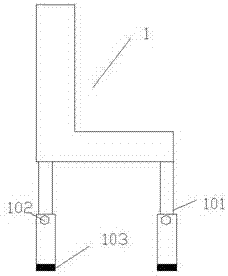
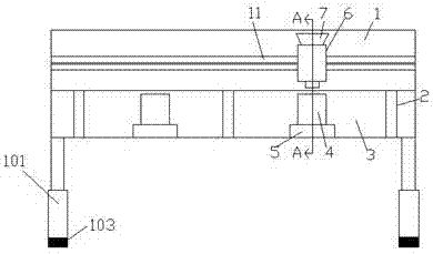
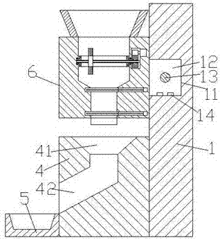
[0022] Such as Figure 1-Figure 4 As shown, a stirring device of the present invention includes a workbench 1, and the four corners of the bottom of the workbench 1 are provided with lifting rods 101, and the middle end of the left end surface of the lifting rod 101 is provided with a tightening member 102. , the bottom of the lifting rod 101 is provided with an anti-skid pad 103, and the height of the lifting rod 101 can be adjusted according to the height of the operator through the tightening member 102, so as to achieve an ideal working height and make the operation more labor-saving. The anti-slip mat 103 can effectively prevent the lifting rod 101 from slipping when it is supported due to the wet and slippery ground, and improves the stability when it is supported. Groove 11, in the sliding groove 11, a guide block 12 is slidably connected, and the front end surface of the guide block 12 is fixedly provided with a container 6, and the top of the container 6 is provided w...


PUM


Abstract

The invention discloses a stirring device. The stirring device comprises a workbench. Four corners at the bottom of the workbench are provided with lifting rods at the same time. The end face of the left side of each lifting rod is provided with a screwing component. The bottom of the lifting rod is provided with a non-slip mat. The front end face of the workbench is provided with a leftwards and rightwards extended sliding channel. A movement guiding block is slidably matched and connected in the sliding channel. The end face of the front side of the movement guiding block is fixedly provided with a container. The top of the container is provided with a funnel. The interior of the container is successively provided with a first cavity, a triangle cavity and a second cavity from top to bottom. A manipulating cavity is installed in the container at the rear side of the first cavity. A forwards and backwards extended rotation rod is installed in the first cavity. The tail parts of the front and rear sides of the rotation rod are provided with steering shafts extended forwards and backwards. The backwards extended section of the steering shaft passes through the wall body of the container and is extended into the manipulating cavity. The tail part, extended into the manipulating cavity, of the steering shaft is provided with a first tooth-shaped wheel. The end of the interior of the rotation rod is provided with a forwards and backwards extended hole which successively passes through the steering shaft and the first tooth-shaped wheel. A first spiral rod is installed in the hole. The structure of the stirring device is simple, the control is automatic, the operation is convenient, the stirring and output work can be automatically realized, the working efficiency is improved, and the labor intensity of an operator is reduced.

Description

technical field [0001] The invention relates to the technical field of stirring equipment, in particular to a stirring device. Background technique [0002] Eggs are one of people's favorite and most common foods. Because of their rich nutritional value, they are often used as the main ingredient in pastry making, especially in pastry processing rooms. However, eggs need to be cleaned before being processed and used. It is crushed and stirred evenly. Since many people are used to process at the same time in the processing room, the amount of use is large. Manual stirring is not only time-consuming and labor-intensive, but also difficult to keep up with the processing progress. Affect the mouthfeel of processed food, there is bigger drawback, be difficult to satisfy existing needs. Contents of the invention [0003] The technical problem to be solved by the present invention is to provide a homogenizing device, which can solve the above-mentioned problems in the prior art....

Claims


Application Information

Patent Timeline
IPC IPC(8): A23P30/40
Inventor 鲁洁锋
Owner 湖北京山楚天钡盐有限责任公司
Why Eureka
Eureka Blog
Learn More