
Metal sheet compression moulding device

A technology of pressing and forming metal sheets, which is applied in the field of mechanical processing, can solve problems such as affecting product processing efficiency, discontinuous processing, and complicated equipment, and achieve the effects of simplifying equipment, improving processing quality, and facilitating loading

Active Publication Date: 2017-06-30
YANCHENG DAJIE IND CO LTD
View PDF8 Cites 0 Cited by
  • Summary
  • Abstract
  • Description
  • Claims
  • Application Information

AI Technical Summary

Problems solved by technology

[0002] In the field of mechanical processing, the press-forming device is also one of the essential equipment. The press-forming device is generally used for the processing of metal sheets. The metal sheet forms a specific shape under the action of the press-forming device to meet the needs of use. The molding device is generally equipped with a mold cavity with a characteristic shape and a die head that matches the mold cavity. Before the die head moves, the metal sheet needs to be pressed tightly, so as to facilitate the pressing of the metal sheet. , because the molded product will be stuck in the mold cavity, when taking out the molded product, it is necessary to use the ejector pin to take it out smoothly, but the traditional pressing device is generally equipped with a pressing device and an ejecting device separately, which will cause the complexity of the equipment. At the same time, the processing process of the product is discontinuous, which will affect the processing efficiency of the product

Method used


Image

  • Metal sheet compression moulding device
  • Metal sheet compression moulding device
  • Metal sheet compression moulding device

Examples


Embodiment Construction

[0020] All features disclosed in this specification, or steps in all methods or processes disclosed, may be combined in any manner, except for mutually exclusive features and / or steps.

[0021] Any feature disclosed in this specification (including any appended claims, abstract and drawings), unless expressly stated otherwise, may be replaced by alternative features which are equivalent or serve a similar purpose. That is, unless expressly stated otherwise, each feature is one example only of a series of equivalent or similar features.

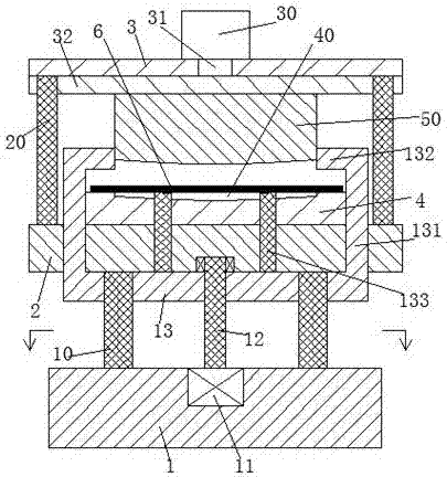
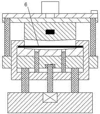
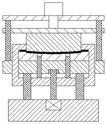
[0022] Such as Figure 1-4 As shown, a sheet metal pressing and forming device of the present invention is used to press and form sheet metal parts 6, including a machine base 1, a workbench 2 and a top plate 3, the upper end of the workbench 2 is fixed, and the forming seat 4 is provided with A molding cavity 40 with an opening facing upwards, at least two lower guide pillars 10 are fixedly installed between the machine base 1 and the workbe...


PUM


Abstract

The invention discloses a metal sheet compression moulding device for compression moulding of a metal sheet. The metal sheet compression moulding device comprises a machine base, a working table and a top plate, wherein a moulding base is fixedly mounted at the upper end of the working table; a moulding cavity with an upward opening is formed in the moulding base; at least two lower guide pillars are fixedly mounted between the machine base and the working table; at least two upper guide pillars are fixedly mounted between the working table and the top plate; a lifting plate is mounted on each lower guide pillar in a sliding manner; lifting arms are arranged at the upper ends of two sides of the lifting plate; the upper end of each lifting arm penetrates through the working table to extend upwards; a clamping arm extends towards the middle is arranged at the upper end of the lifting arm; a lifting threaded rod is mounted in the center of the lifting plate in a screw-thread fit manner; at least two through holes communicating with the moulding cavity are formed in the moulding base and the working table; ejector rods are mounted in the through holes in a sliding manner; the lower ends of the ejector rods are fixedly connected with the lifting plates; and a moulding mechanism is further mounted on the top plate.

Description

technical field [0001] The invention relates to the field of mechanical processing, in particular to a metal plate pressing and forming device. Background technique [0002] In the field of mechanical processing, the press-forming device is also one of the essential equipment. The press-forming device is generally used for the processing of metal sheets. The metal sheet forms a specific shape under the action of the press-forming device to meet the needs of use. The molding device is generally equipped with a mold cavity with a characteristic shape and a die head that matches the mold cavity. Before the die head moves, the metal sheet needs to be pressed tightly, so as to facilitate the pressing of the metal sheet. , because the molded product will be stuck in the mold cavity, when taking out the molded product, it is necessary to use the ejector pin to take it out smoothly, but the traditional pressing device is generally equipped with a pressing device and an ejecting devi...

Claims


Application Information

Patent Timeline
IPC IPC(8): B21D22/02B21D43/00B21D45/04
CPCB21D22/02B21D43/003B21D45/04
Inventor 任伟飞
Owner YANCHENG DAJIE IND CO LTD
Features
  • Generate Ideas
  • Intellectual Property
  • Life Sciences
  • Materials
  • Tech Scout
  • Unparalleled Data Quality
  • Higher Quality Content
  • 60% Fewer Hallucinations
Learn More