Core-taking system for automatic segmented deslagging and rock core truncation and using method thereof

An automatic segmentation and core technology, which is applied in earthwork drilling, undisturbed core extraction devices, wellbore/well components, etc., can solve the problems of core remaining inside the drill hole, drill sticking, serious problems, etc., to overcome coal Rock slag and core cannot be cut off, the application is safe and reliable, and the application is easy to operate

Inactive Publication Date: 2017-06-30
CHINA UNIV OF MINING & TECH
View PDF5 Cites 11 Cited by
  • Summary
  • Abstract
  • Description
  • Claims
  • Application Information

AI Technical Summary

Problems solved by technology

This method is widely used because of its simple structure and single operation of the coring tube. However, a serious defect of this method is that the coal and rock slag in the deep hole cannot be effectively discharged when the core tube is drilled to a certain depth. As a result, drill sticking and serious dust phenomena often occur during the drilling process, so workers have to wear layers of tight dust masks, which seriously affects work efficiency.
[0004] Due to the existence of the above problems, a coring tube that utilizes water to flush the coal and rock slag in the borehole has been designed. There is a certain amount of coal and rock slag, but it is still incapable of coring at a long distance of more than 5m, and the problem of drill sticking is still prominent, resulting in a large number of drill holes being wasted halfway
[0005] In addition to the above-mentioned problems, there is another key problem that when the core pipe reaches a certain depth in the hard coal rock formation, it is difficult to cut off the deep core along its bottom. Therefore, after the core pipe is taken out, the core remains The embarrassing situation inside the drill hole, which has to be driven by the drilling rig to swing up and down and left and right many times in order to break the core and take it out
This not only seriously affects the efficiency of imaging work, but also greatly reduces the service life of related equipment.

Method used


Image

  • Core-taking system for automatic segmented deslagging and rock core truncation and using method thereof
  • Core-taking system for automatic segmented deslagging and rock core truncation and using method thereof
  • Core-taking system for automatic segmented deslagging and rock core truncation and using method thereof

Examples


Embodiment

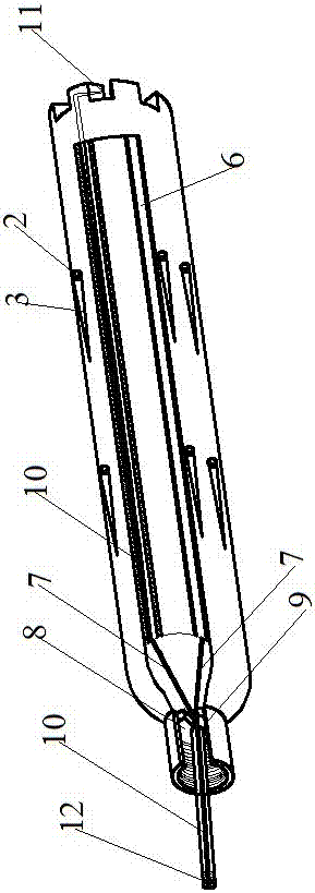
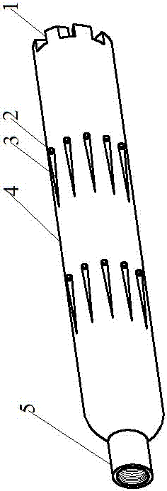
[0042] like figure 1 As shown, the core pipe 4 includes two rows of drainage holes 2 and six cutting teeth 1, the two rows of drainage holes 2 divide the pipe body into three equal parts, and the six cutting teeth 1 are located on the circumference of the pipe body. point; the middle of the core tube 4 is provided with a section of hollow part, that is, the low-pressure water chamber 6; the tail end of the core tube 4 is the connection end with the special drilling rig 16 head, and is provided with an internal thread, which can make the low pressure The water pipe 9 passes through the high-pressure water pipe 10, and the internal thread is used to connect with the machine head connection end 15 of the drilling rig.

[0043] One of the six cutting teeth 1 is provided with a high-pressure water cutting hole 11 , and the high-pressure water cutting hole 11 communicates with the low-pressure water chamber 6 .

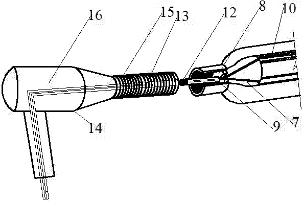
[0044] The connecting end 15 of the head of the special drilling rig ...


PUM


Abstract

The invention relates to a core-taking system capable of achieving automatic segmented deslagging and rock core truncation in a roadway and a using method thereof. The core-taking system comprises a core-taking pipe, a dedicated drilling machine, a high-low-pressure three-way connector and a water pressure pressurizing pump; the core-taking pipe is connected with the dedicated drilling machine, the high-low-pressure three-way connector is connected with the dedicated drilling machine, and low-pressure water used for deslagging and high-pressure water used for rock core truncation are provided for core-taking operation. In the using process, coal and rock fragments of the deep positions of drill holes can be automatically and effectively discharged, truncation can be automatically conducted on rock cores in the deep positions of the drill holes, and the defects that through a traditional core-taking pipe, coal and rock fragments in the deep positions are difficultly discharged, and rock core truncation cannot be achieved are overcome.

Description

technical field [0001] The invention relates to the field of mine roadway engineering tools, in particular to a coring system capable of automatically segmentally discharging slag and cutting rock cores in the roadway and a method for using the same. Background technique [0002] Coring in coal mine roadway refers to the process of rock sampling for the roadway surrounding rock in order to understand the overall condition of the roadway surrounding rock mass. [0003] At present, the coring in the roadway is completed through the cooperation of the coring tube and the drilling rig. The traditional coring tube is connected to the connecting end of the drill pipe of the drilling rig. out. This method is widely used because of its simple structure and single operation of the coring tube. However, a serious defect of this method is that the coal and rock slag in the deep hole cannot be effectively discharged when the core tube is drilled to a certain depth. As a result, drill ...

Claims


Application Information

Patent Timeline
Patent Type & Authority Applications(China)
IPC IPC(8): E21B25/00E21B25/10E21B21/00
CPCE21B21/00E21B25/00E21B25/10
Inventor 郭玉郑西贵郭罡业王延庆卢卫永何风贞
Owner CHINA UNIV OF MINING & TECH
Why Eureka
Try Eureka