Wire winding device arranged between tin soldering power line core and varnished wire

A technology for power cords and enameled wires, applied in circuits, electrical components, cable/conductor manufacturing, etc., can solve problems such as soldering quality that affects the quality of wire wrapping, not very practical, tremor errors, etc., to achieve simple structure, simple control, and avoidance. The effect of virtual welding

Active Publication Date: 2017-06-30
JIANGSU YALUO TECH
View PDF4 Cites 0 Cited by
  • Summary
  • Abstract
  • Description
  • Claims
  • Application Information

AI Technical Summary

Problems solved by technology

[0002] The wire winding machine is a kind of twisting mechanical equipment that can be widely used in various types of soft / hard conductor wires, so that multiple single conductors can be twisted into one strand to meet the technical requirements of the wire. It is not very practical when it is used, because many of the ends of the power cord of the motor are soldered. superior
[0003] At present, in the process of motor production and production, it is necessary to wrap the wire at the joint of the motor. When winding the wire, because many power cord ends of the motor are soldered, and the power cord after soldering is relatively hard. The winding operation can improve the quality of the winding wire and avoid false soldering during soldering before and after production. However, the existing operations are generally done manually. Although the quality of the winding wire is improved compared to when there is no solder, it is after all Manual winding, trembling will cause mistakes, resulting in loose winding, which affects the quality of winding and the quality of soldering tin later

Method used


Image

  • Wire winding device arranged between tin soldering power line core and varnished wire
  • Wire winding device arranged between tin soldering power line core and varnished wire
  • Wire winding device arranged between tin soldering power line core and varnished wire

Examples


Embodiment Construction

[0016] The technical solution of this patent will be further described in detail below in conjunction with specific embodiments.

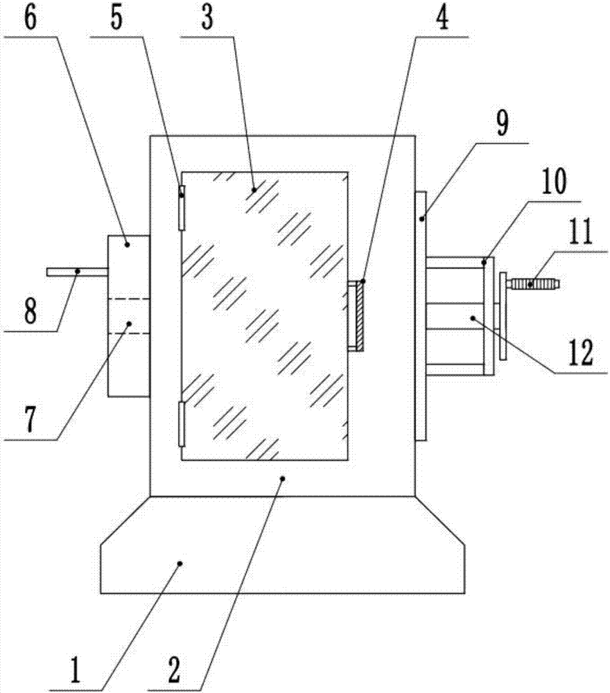
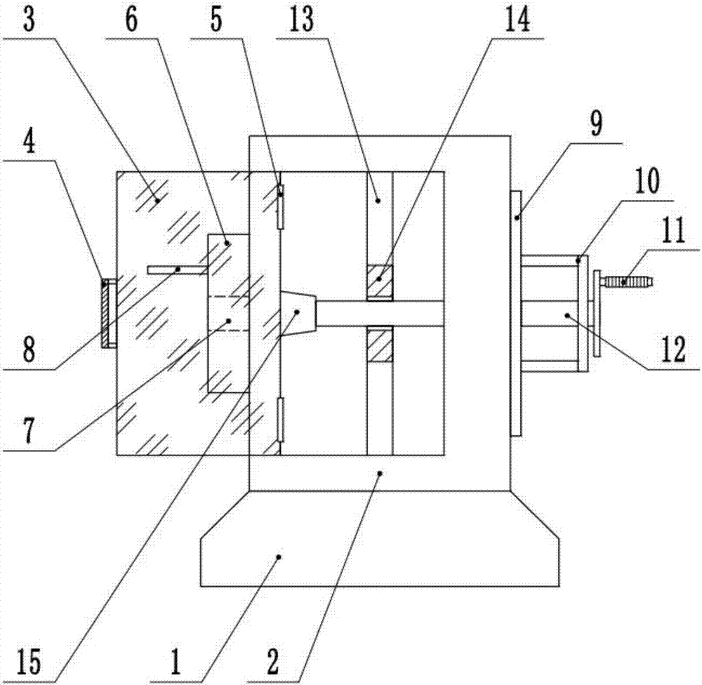
[0017] see Figure 1-3 , a wire winding device for soldering between a power cord core and an enameled wire, comprising a device body, a base 1 is provided at the bottom of the device body, a housing 2 is provided above the base 1 , and the housing 2 and the base 1 are Fixedly connected by welding, the shell 2 is a hollow structure, the front of the shell 2 is provided with an observation window 3, and the observation window 3 and the shell 2 are rotatably connected by the function of the hinge 5, and the observation window 3 The handle 4 is set on the right side of the handle 4, and the handle 4 is fixedly connected with the observation window 3 through the action of the fixing screw, and the observation window 3 and the shell 2 are snapped and connected through the buckle, and the left side of the shell 2 A plug-in positioning plate 6 is arrange...


PUM


Abstract

The invention discloses a wire winding device arranged between a tin soldering power line core and a varnished wire. The wire winding device comprises a device body, a base is arranged at the bottom of the device body, a shell is arranged on the base, the front face of the shell is provided with an observation window, the left side of the shell is provided with an insertion positioning plate, and the right side of the shell is provided with a support; a fixing frame is arranged on the support, a rotating shaft is arranged in the middle of the fixing frame, a wire winding cover is arranged at the end of the left side of the rotating shaft, a bottom plate is arranged at the bottom of the wire winding cover, a side plate is arranged on the side wall of the wire winding cover, a positioning column is arranged on the inner side wall of the bottom plate, a groove is formed in the top of the positioning column, a connecting rod is arranged on the side wall of the positioning column, and a wire retaining rod is arranged at the end of the connecting rod. The wire winding device is simple in structure and easy to control, the varnished wire is wound on the power line core and distributed uniformly and compactly, the wire winding quality is good, the faulty soldering phenomenon occurring during subsequent tin soldering is effectively avoided, the tin soldering quality is guaranteed, use is convenient, and the practicability is high.

Description

technical field [0001] The invention relates to the field of mechanical processing, in particular to a wire winding device between a soldering power cord core and an enameled wire. Background technique [0002] The wire winding machine is a kind of twisting mechanical equipment that can be widely used in various types of soft / hard conductor wires, so that multiple single conductors are twisted into one strand to meet the technical requirements of the wire. It is not very practical when it is used, because many of the ends of the power cord of the motor are soldered. superior. [0003] At present, in the process of motor production and production, it is necessary to wrap the wire at the joint of the motor. When winding the wire, because many power cord ends of the motor are soldered, and the power cord after soldering is relatively hard. The winding operation can improve the quality of the winding wire and avoid false soldering during soldering before and after production. ...

Claims


Application Information

Patent Timeline
Patent Type & Authority Applications(China)
IPC IPC(8): H01B13/02
CPCH01B13/0207H01B13/0235
Inventor 不公告发明人
Owner JIANGSU YALUO TECH
Why Eureka
Try Eureka