Quick coupling and working method thereof

A fast, male plug technology, applied in the direction of mechanical equipment, couplings, etc., can solve the problems of impact water seepage, plugging and unplugging with less leakage, etc., to achieve the effect of ensuring fast circulation, easy mating, and avoiding leakage

Active Publication Date: 2017-07-04
丹阳市裕桥精密元件有限公司
View PDF6 Cites 4 Cited by
  • Summary
  • Abstract
  • Description
  • Claims
  • Application Information

AI Technical Summary

Problems solved by technology

Existing fluid connector products can realize quick connection, and have both non-return and one-way sealing functions, but few can be plugged and unplugged without leakage, and existing products also have adverse problems such as impact water seepage

Method used


Image

  • Quick coupling and working method thereof
  • Quick coupling and working method thereof
  • Quick coupling and working method thereof

Examples


Embodiment 1

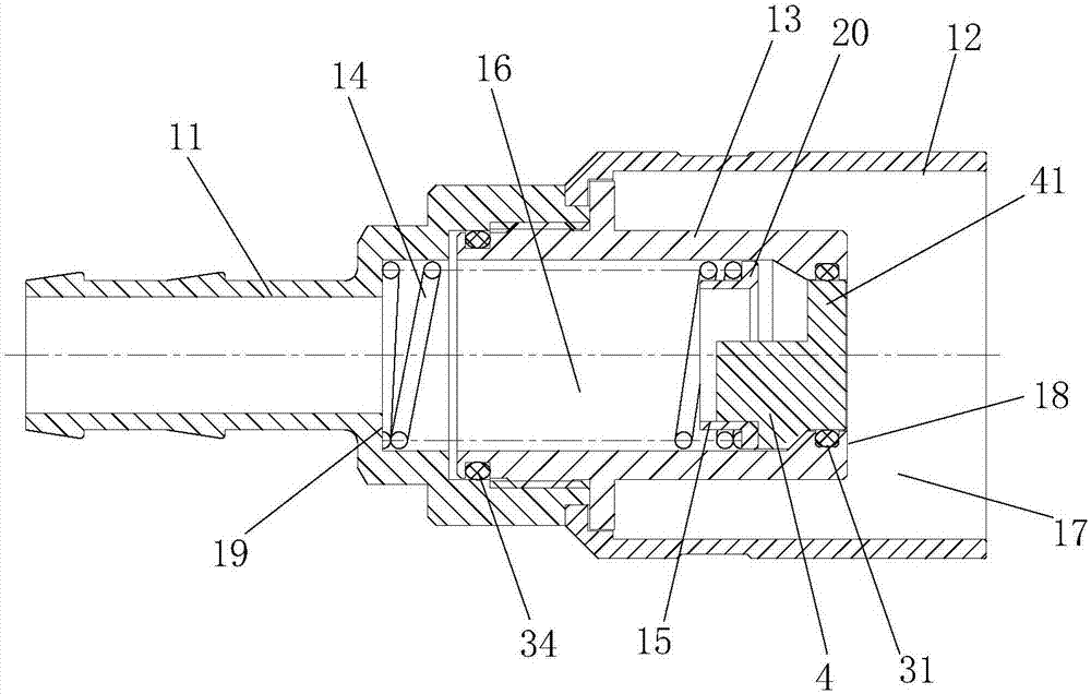
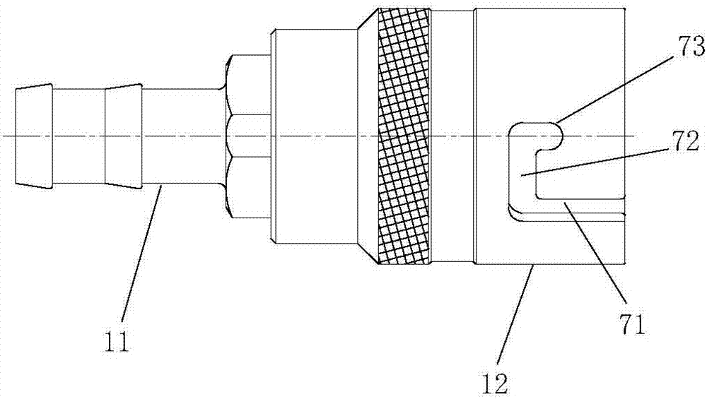
[0028] Embodiment 1 The quick connector of this embodiment includes a plug-fit male plug and a female plug (for the convenience of discussion, when referring to the front end, the components in the male plug refer to the end near the connection between the male plug and the female plug, and the opposite end is the tail end; when referring to the tail end, the parts in the female plug refer to the end near the connection between the male plug and the female plug, and the opposite end is the front end); figure 1 As shown, the male plug includes a first sleeve 11 of the male plug, a second sleeve 12 of the male plug, and a third sleeve 13 of the male plug. In the tail end of the third sleeve 13 of the male plug, the tail end of the third sleeve 13 of the male plug is sealed and sleeved in the front end of the first sleeve 11 of the male plug, and a fourth annular groove is arranged on the outer wall of the tail end of the third sleeve 13 of the male plug. A fourth O-ring 34 is ar...

Embodiment 2

[0037] The working method of quick coupling as described in embodiment 1, comprises the steps:

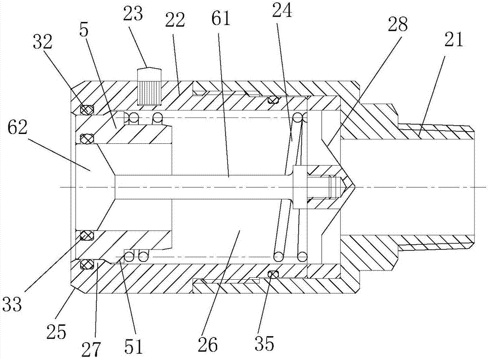
[0038] A. When the male plug is in the initial state, the first spring 14 supports the first valve core 4 to reach the front end of the third sleeve 13 of the male plug, and the annular side wall of the first sealing disc 41 and the third sleeve 13 of the male plug An annular sealing part 18 is sealed and fitted through the first O-ring 31, so that the male plug is in a closed state; when the female plug is in the initial state, the second spring 24 supports the second valve core 5 to reach the end of the second sleeve 22 of the female plug end, the outer wall of the second spool 5 seals with the second annular sealing portion 27 of the second sleeve 22 of the female plug through the second O-ring 32 , and the inner wall of the second spool 5 passes through the third O-ring 33 It is sealingly matched with the annular side wall of the second sealing disc 62, so that the female plug ...


PUM


Abstract

The invention relates to a quick coupling and a working method thereof. The quick coupling comprises a male connector and a female connector which are connected and matched with each other in a plugged mode. The male connector and the female connector are internally provided with a movably first valve element and a movable second valve element correspondingly, and the first valve element and the second valve element are in sealing fit with annular sealing parts of sleeves correspondingly. The quick coupling is simple in structure. After the male connector and the female connector are plugged together, the second annular sealing part is in sealing fit with a third sleeve of the male connector to effectively avoid leakage. A herringbone guide support is arranged to guarantee that the first valve element cannot get inclined when sliding in the third sleeve of the male connector, and guiding is stable. Meanwhile, the outer edge of the herringbone guide support protrudes out of the edge of a first sealing disk so that a channel suitable for circulation of liquid with pressure can be formed easily after the first sealing disk slides towards the third sleeve of the male connector, and quick circulation of the liquid with pressure is guaranteed.

Description

technical field [0001] The invention relates to the technical field of heat dissipation equipment for electronic products, in particular to a quick connector and a working method thereof. Background technique [0002] The application of liquid cooling technology in the field of heat dissipation of electronic products is inseparable from the development of connection technology. Fluid connection technology has become the key to restricting its development. It is required that the connector can be plugged and unplugged without leakage, fast connection, and has the function of non-return and one-way sealing. Fluid connector, also known as quick connector, is a connector that can realize pipeline fluid connection or disconnection without tools. It consists of two parts, a male plug and a female plug. The male plug and the female plug are each equivalent to a one-way There is a spool inside the valve. When it is not inserted, the one-way valve is closed under the action of the s...

Claims


Application Information

Patent Timeline
IPC IPC(8): F16L37/248F16L37/36
CPCF16L37/248F16L37/36
Inventor 蒋于良李中和杜振
Owner 丹阳市裕桥精密元件有限公司
Why Eureka
Try Eureka