Enclosed pressure-limiting valve of pressure cooker and pressure cooker

A pressure limiting valve and pressure cooker technology, applied in pressure cookers, special materials for cooking utensils, cooking utensils, etc., can solve problems such as affecting user experience, continuous exhaust of pressure limiting valve, irregular swing, etc., to improve cooking quality and avoid abnormality Pressure relief, product stable and reliable effect

Inactive Publication Date: 2017-07-07
JOYOUNG CO LTD
View PDF8 Cites 2 Cited by
  • Summary
  • Abstract
  • Description
  • Claims
  • Application Information

AI Technical Summary

Problems solved by technology

Specifically, when the pressure rises and the pressure limiting valve is slightly lifted, the gas is ejected from the gap between the valve core and the exhaust port of the exhaust pipe, and hits the inner wall of the exhaust cavity of the pressure limiting valve, causing the pressure limiting The valve swings left and right, and its swing is irregular, which may also cause the pressure limiting valve to tilt and cannot be reset to the initial sealing state, resulting in continuous exhaust, affecting user experience

Method used


Image

  • Enclosed pressure-limiting valve of pressure cooker and pressure cooker
  • Enclosed pressure-limiting valve of pressure cooker and pressure cooker
  • Enclosed pressure-limiting valve of pressure cooker and pressure cooker

Examples


Embodiment 1

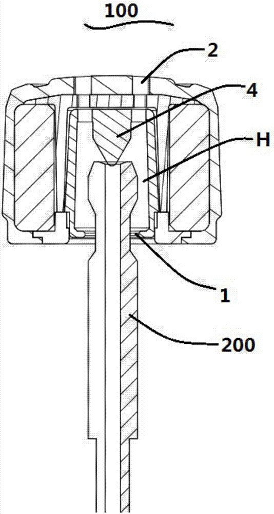
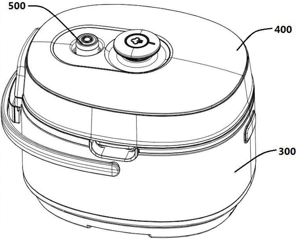
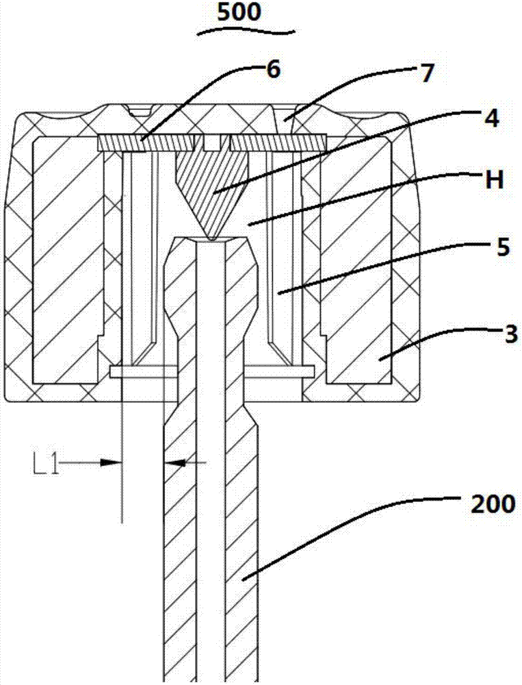
[0032] The present invention proposes a kind of pressure cooker, can refer to Figure 2-Figure 4 , comprising a pot body 300 and a pot cover 400, the pot cover 400 is provided with an exhaust pipe 200 and a pressure limiting valve installed in cooperation with the exhaust pipe 200, the pressure limiting valve is a closed pressure limiting valve 500, the pressure limiting valve The valve 500 includes a valve body 3, the weight of the pressure limiting valve is 50-100 grams, the valve body 3 is formed with an exhaust chamber H with a lower end opening 1, and the exhaust pipe 200 extends into the exhaust chamber H, the top wall of the exhaust chamber H is provided with a valve core 4, the valve core 4 seals the exhaust port of the exhaust pipe 200, the side wall of the exhaust chamber H is provided with ribs, and the air flow of the exhaust pipe 200 is lifted The valve core 4 blows to the rib to drive the valve body 3 to rotate and exhaust, and the gap between the side wall of th...

Embodiment 2

[0039] The pressure limiting valve 600 of this embodiment can refer to Figure 5 In this embodiment, on the basis of the first embodiment, the upper end of the side wall of the exhaust chamber H is provided with a stepped portion 8 . That is, the stepped portion 8 is located at the joint between the side wall and the top wall of the exhaust chamber H. The upper end of the step portion 8 is in contact with the top wall of the exhaust chamber H, so that the step portion 8 can be easily manufactured out of the mold. Preferably, the exhaust port of the exhaust pipe 200 is lower than the step portion 8 , and since the valve core 4 seals the exhaust port of the exhaust pipe, the lowest point of the valve core 4 is lower than the step portion 8 . During high-pressure cooking, the gas in the exhaust pipe 200 is discharged after the valve core 4 is pushed up, and most of its initial direction is obliquely upward, and the step part 8 is just above the exhaust port, so the exhausted air...


PUM


Abstract

The invention provides an enclosed pressure-limiting valve of a pressure cooker. The pressure-limiting valve comprises a valve body; the pressure-limiting valve is 50-100g in weight; an exhaust cavity is formed in the valve body; a valve element is arranged on the top wall of the exhaust cavity; convex ribs are arranged on the sidewalls of the exhaust cavity; and an airflow, which ejects the valve element, is blown towards the convex ribs, so that the valve body is driven to rotate to conduct exhausting. By arranging the convex ribs on the sidewalls of the exhaust cavity, original exhaust cavity sidewalls, which are represented as regular curved surfaces, are changed; and when high-pressure exhausting is conducted, the airflow is blown towards the convex ribs and the airflow is stopped by the convex ribs in a horizontal direction, so that the valve body, on the basis of action force in the horizontal direction, is rotated. The invention also provides the pressure cooker provided with the enclosed pressure-limiting valve.

Description

technical field [0001] The invention relates to the field of kitchen cooking utensils, in particular to a closed pressure limiting valve of a pressure cooker and a pressure cooker. Background technique [0002] The pressure cooker cooks in a higher than normal pressure environment. The lid of the pressure cooker is generally provided with an exhaust pipe, and a pressure limiting valve is arranged on the exhaust pipe. Realize the sealing of the exhaust pipe to achieve the purpose of high-pressure cooking. After cooking, when the pressure is lowered and the cover is opened, the pressure limiting valve is acted on by the exhaust ejector rod or the solenoid valve, and the pressure limiting valve is tilted or lifted to release the seal of the exhaust pipe, so as to realize the exhaust and pressure reduction. [0003] Depending on whether there is an air outlet on the top, the pressure limiting valve can be divided into an open pressure limiting valve and a closed pressure limiti...

Claims


Application Information

Patent Timeline
Patent Type & Authority Applications(China)
IPC IPC(8): A47J27/09A47J36/38A47J36/04A47J36/02
CPCA47J27/09A47J36/02A47J36/04A47J36/38
Inventor 朱泽春李云昊陆黎
Owner JOYOUNG CO LTD
Why Eureka
Try Eureka