Leg fracture traction frame

A traction frame and leg technology, applied in the field of leg fracture traction frame, can solve problems such as poor use effect, inconvenient adjustment, complex structure, etc., and achieve the effect of simple structure, simplified structure and low cost

Inactive Publication Date: 2017-07-07
梁艳
View PDF0 Cites 3 Cited by
  • Summary
  • Abstract
  • Description
  • Claims
  • Application Information

AI Technical Summary

Problems solved by technology

[0002] For patients with leg fractures, traction is usually required during treatment. The traction device currently used is a special traction bed, which has a comple

Method used


Image

  • Leg fracture traction frame
  • Leg fracture traction frame
  • Leg fracture traction frame

Examples


Embodiment Construction

[0026] The principles and features of the present invention will be described below with reference to the accompanying drawings. The examples cited are only used to explain the present invention, and are not used to limit the scope of the present invention.

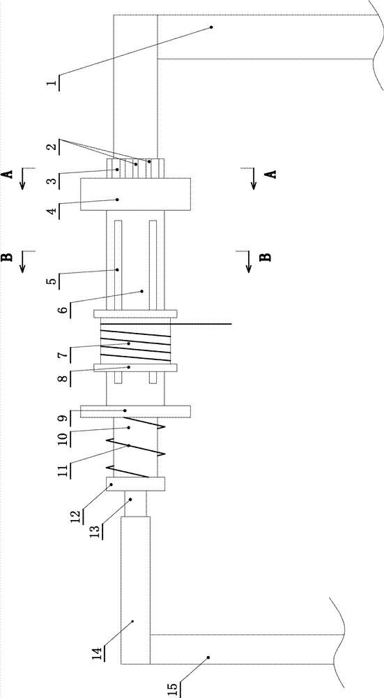
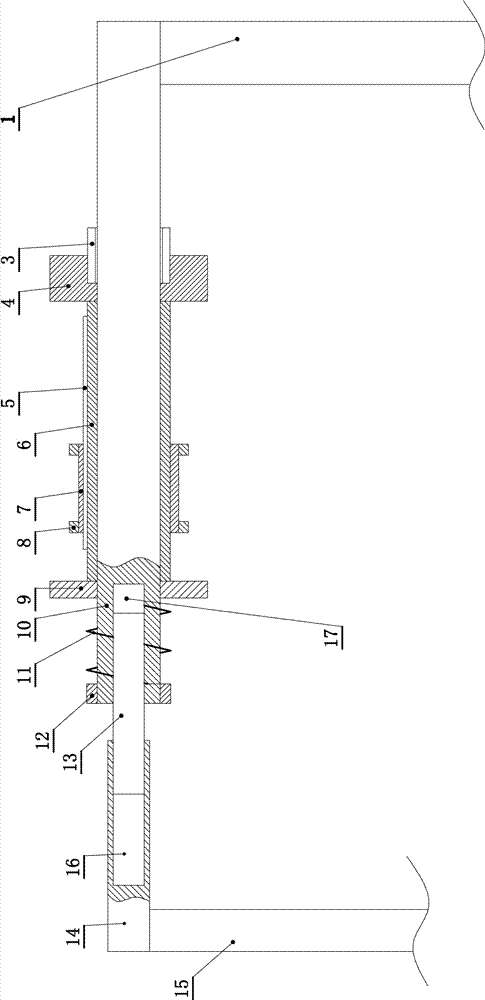
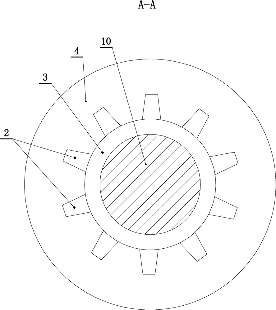
[0027] Such as Figure 1 to Figure 10 As shown, a leg fracture traction frame includes a main frame (1), the main frame (1) is an inverted "V" shape, and the main frame (1) is fixedly connected with a horizontally arranged main support beam (10), The main support beam (10) is fixedly connected with a positioning stop (3), and the main support beam (10) outside the positioning stop (3) slides left and right, and is connected with a positioning ring (4) and a positioning ring (4). ) The outer side is fixedly connected with a rotating roller (6). The rotating roller (6) and the main support beam (10) are also slid left and right and connected in relative rotation. The positioning ring (4) has a main beam perforation (19) in the...


PUM


Abstract

A leg fracture traction frame, the main support beam is fixedly connected with a positioning block, the main support beam outside the positioning block slides left and right, and is connected with a positioning ring for relative rotation, and a rotating roller is fixedly connected to the outside of the positioning ring, and the rotating roller The main support beam is also sliding left and right and connected with relative rotation. There is a main beam perforation in the middle of the positioning ring. The main support beam moves through the main beam perforation. After the positioning ring contacts the positioning stopper, the positioning stopper restricts the positioning ring Rotate with the rotating roller; the outer side of the rotating roller slides left and right and is connected with a rope-wrapped hanging roller. , the spring is always in sliding contact with the outer end of the roller. One end of the spring is fixedly connected to the free end of the main support beam outside the roller, and the other end of the spring is fixedly connected to a movable retaining ring, which is always in sliding contact with the outer side of the roller.

Description

Technical field [0001] The invention relates to a medical device, in particular to a leg fracture traction frame. Background technique [0002] For patients with leg fractures, traction is usually required during treatment. The current traction device used is a special traction bed, which is complicated in structure and expensive. Some hospitals only use simple stents for traction, but the controllability is poor. It is inconvenient to adjust, so the use effect is not good. Summary of the invention [0003] Aiming at the disadvantages, the invention provides a leg fracture traction frame with simple structure, low cost, convenient adjustment and control, and good use effect. [0004] The technical solutions of the present invention to solve the above technical problems are as follows: [0005] A traction frame for leg fractures, comprising a main frame on which a horizontally arranged main support beam is fixedly connected, characterized in that a positioning stopper is fixedly conn...

Claims


Application Information

Patent Timeline
IPC IPC(8): A61F5/042
CPCA61F5/042
Inventor 梁艳
Owner 梁艳
Why Eureka
Try Eureka