
Pneumatic pipe continuous transferring system

A technology of transmission system and pneumatic pipeline, which is applied in the direction of conveyor, transportation and packaging, etc., can solve the problem of low transmission efficiency, and achieve the effect of improving transmission efficiency and increasing transmission efficiency

Active Publication Date: 2017-07-07
XIAMEN SAIMO JISHUO TECH CO LTD
View PDF7 Cites 3 Cited by
  • Summary
  • Abstract
  • Description
  • Claims
  • Application Information

AI Technical Summary

Problems solved by technology

[0011] The present invention aims to provide a pneumatic pipeline continuous transmission system to solve the problem of low transmission efficiency of the existing pneumatic pipeline transmission system

Method used


Image

  • Pneumatic pipe continuous transferring system
  • Pneumatic pipe continuous transferring system
  • Pneumatic pipe continuous transferring system

Examples


Embodiment 1

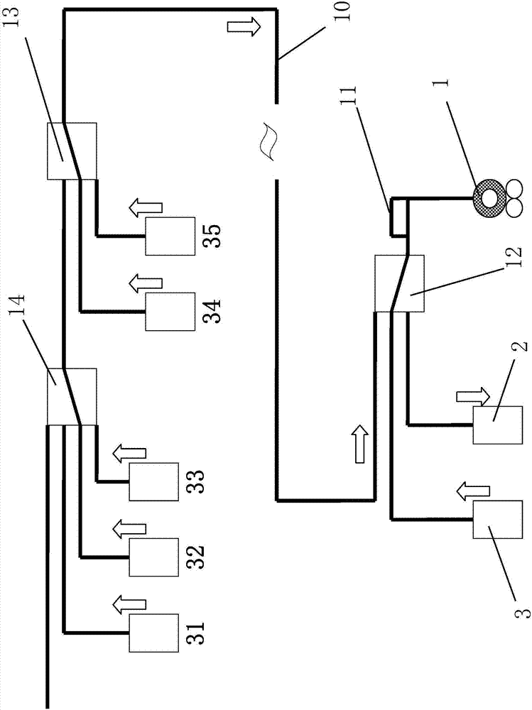
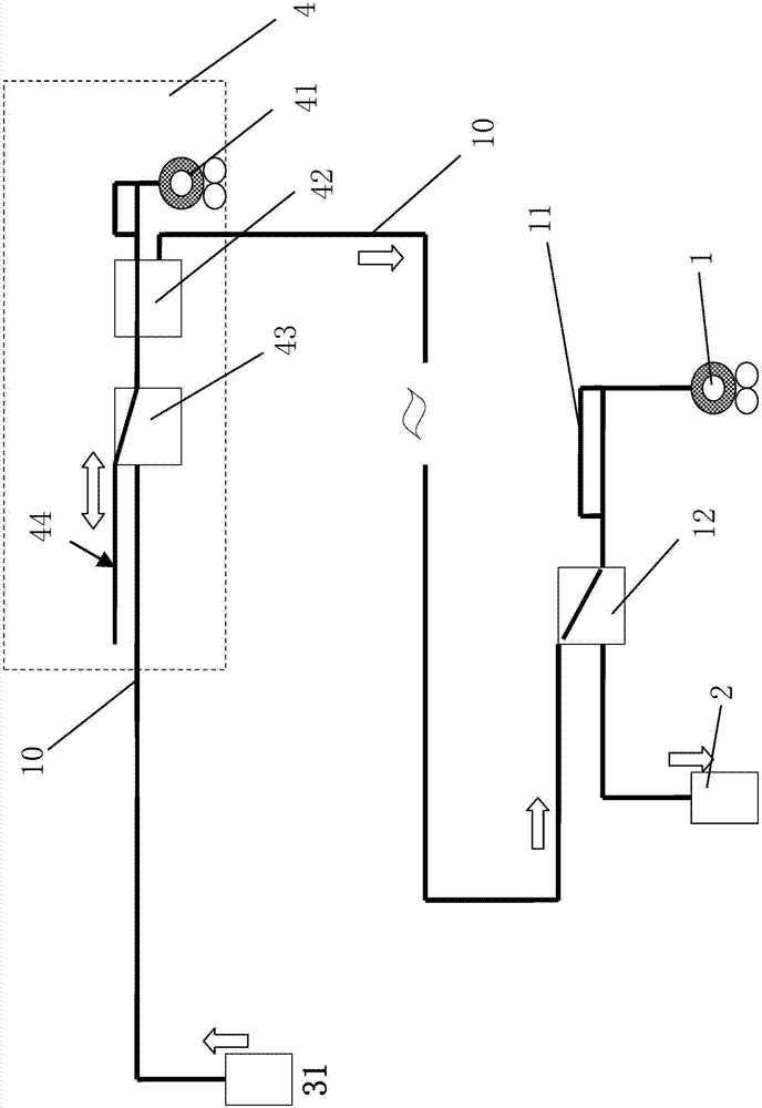
[0035] This embodiment discloses a pneumatic pipeline continuous transmission system, including a receiving workstation 2, a sending workstation 31 and a main fan 1, the receiving workstation 2 and the sending workstation 31 are connected through a main pipeline 10, and the receiving workstation 2 and the sending workstation 31 are connected to a storage converter 12 through the main pipeline 10, and then connected to the main fan 1 after passing through the storage converter 12, and on the main pipeline 10 between the main fan 1 and the storage converter 12 A main bypass pipe 11 is also provided.

[0036] The main pipeline 1 is connected in series with a relay transceiver system 4, and the relay transceiver system 4 includes a first converter 43, a second converter 42, a temporary storage pipeline 44 and a relay fan 41:

[0037] The first and second converters 43, 42 are first connected in series, and then connected in series to the main pipeline 10, the temporary storage pip...

Embodiment 2

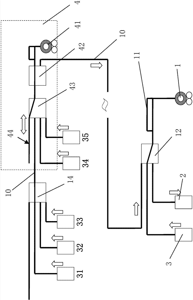
[0045] combine image 3 As shown, this embodiment discloses a pneumatic pipeline continuous transmission system, including receiving workstation 2, sending workstation 3, sending workstations 31-35, main fan 1, receiving workstation 2 and each sending workstation are connected through a main pipeline 10, and The receiving workstation 2 and each sending workstation are connected to the main fan 1 through the main pipeline 10; specifically, the main fan 1 is sequentially connected in series with a storage converter 12 and a four-way converter 14 through the main pipeline 10, and then through the storage The converter 12 and the four-way converter 14 are connected to each sending workstation and receiving work 2; in this embodiment, the main bypass pipe 11 is also provided to realize the receiving and sending of the transmission.

[0046] A relay transceiver system 4 is also connected between the storage converter 12 and the four-way converter 14, and the relay transceiver system...

Embodiment 3

[0056] combine Figure 4 As shown, this embodiment is basically the same as embodiment two, and its main difference is:

[0057] In this embodiment, there are two temporary storage pipelines connected to the first converter 43, which are the temporary storage pipeline 44 and the temporary storage pipeline 45; and the main bypass pipe 11 is lengthened to meet the requirements of batch buffering for 2-4 transmissions. bottle.

[0058] If the total time T31+T32+T33+T34 of multiple stations in the transit transceiver system to the temporary storage area is still less than the batch transmission time TB (when the main bypass pipe 11 of the transit transceiver system is far away), more transit transceivers can be added System, when a transit transceiver system is full, it can continue to transmit to the next transit transceiver system.

[0059] The transfer bottles sent to the same destination station of the main bypass pipe 11, such as the receiving workstation 2, can be sent to ...


PUM


Abstract

The invention relates to a pneumatic pipe continuous transferring system. The pneumatic pipe continuous transferring system comprises a receiving workstation, at least one transmitting workstation and a main draught fan. The receiving workstation is connected with the transmitting workstations through a main pipeline, the receiving workstation and the transmitting workstations are connected with the main draught fan through the main pipeline, and the pneumatic pipe continuous transferring system further comprises an interline receiving and transmitting system. The interline receiving and transmitting system is connected into the main pipeline in series, and the two ends, connected with the interline receiving and transmitting system, of the main pipeline are the first main pipeline end and the second main pipeline end correspondingly. The interline receiving and transmitting system comprises a first converter, a second converter, a temporarily storing pipeline and an interline draught fan, the first converter and the second converter are connected into the main pipeline in series after being connected with each other in series, the temporarily storing pipeline is connected with the first converter, and the interline draught fan is connected with the second converter. The first converter is configured to at least switch the second converter and the first main pipeline end or a communicating passageway of the temporarily storing pipeline, and the second converter is configured to at least switch the first converter and the second main pipeline end or a communicating passageway of the interline draught fan.

Description

technical field [0001] The invention discloses a pneumatic pipeline continuous transmission system, which belongs to the technical field of logistics pipeline transmission system manufacturing according to the International Patent Classification Table, and in particular relates to an efficient transmission system for multi-sending workstations or long-distance transmission of multiple bottles in parallel. Background technique [0002] Pneumatic pipeline transmission equipment is mostly used in the field of sample transportation. For example, in the sampling, sample preparation and testing of material (such as ore, coal) samples, it is necessary to transfer and transport the collected samples from the station (laboratory) in this link to The station (laboratory) of the next link is used for the next stage of work. In the process of sample transfer and transportation, pneumatic pipeline transmission has the advantages of good quality control of samples, fast transfer and deliv...

Claims


Application Information

Patent Timeline
Patent Type & Authority Applications(China)
IPC IPC(8): B65G51/04B65G51/32
CPCB65G51/04B65G51/32B65G2201/0244
Inventor 许晓毅周富强
Owner XIAMEN SAIMO JISHUO TECH CO LTD
Learn More