Engine upper cover

An engine and body technology, which is applied to engine components, machines/engines, mechanical equipment, etc., can solve the problems of inability to ensure the correct installation angle of the camshaft, increase structural complexity, and complex cylinder head structure, so as to reduce the weight of the upper cover. Compact structure and the effect of reducing pollutant emissions

Active Publication Date: 2017-07-07
江阴中玮动力机械有限公司
View PDF8 Cites 0 Cited by
  • Summary
  • Abstract
  • Description
  • Claims
  • Application Information

AI Technical Summary

Problems solved by technology

Due to the relatively compact structure of the upper cover, generally the camshaft needs to be fixed with two upper and lower tile covers and bolts during installation, which is inconvenient during installation, and the correct installation angle of the camshaft cannot be ensured, and there is also axial movement, which reduces reliability. , which affects the service life
[0005] 3. The air inlet of the traditional engine cylinder head has multiple flanges connected to the air intake branch respectively, which increases the structural complexity
[0006] 4. The fuel injector of the traditional engine is fixed on the cylinder head
Due to the complex structure of the cylinder head, it is inconvenient to install
[0007] 5. The traditional engine has a separate air intake pipe, and it is not on the upper cover
[0008] 6. There is no oil and gas separation device on the upper cover of the traditional engine, which makes the cylinder head more cumbersome as a whole

Method used


Image

  • Engine upper cover
  • Engine upper cover
  • Engine upper cover

Examples


Embodiment Construction

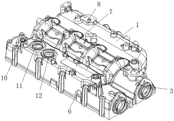
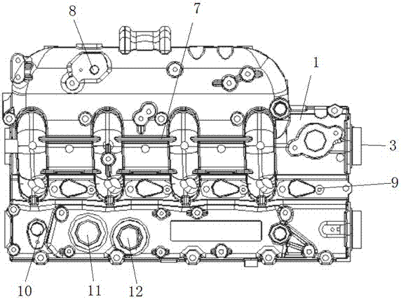
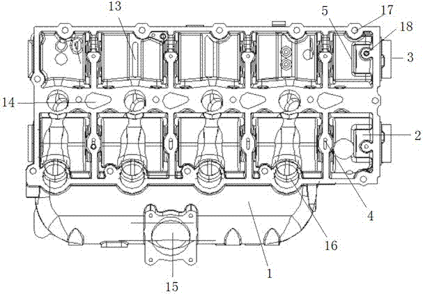
[0034] see Figure 1-Figure 9 , a kind of engine upper cover that the present invention relates to, it comprises upper cover main body 1, and upper cover main body 1 is provided with two transverse camshaft extension bosses 2, and the side of camshaft extension boss 2 close to pulley chamber is arranged There is a camshaft extension boss 3, and the camshaft extension boss 2 protrudes out of the upper cover body 1. When in use, the camshaft extension boss 3 is sealed and installed with the contact part of the pulley chamber, so as to effectively prevent the inflow of liquid, so as to achieve Safe and reliable purpose.

[0035] The bottom surface of the upper cover body 1 is provided with a plurality of oil supply holes 4 corresponding to the two camshaft extension bosses 2. As a preference, each camshaft extension boss 2 corresponds to four oil supply holes evenly arranged. 4. The chute on the surface of the oil supply hole 4 communicates with the cylinder block, so that when ...


PUM


Abstract

The invention relates to an engine upper cover. The engine upper cover comprises an upper cover body. The upper cover body is provided with two transverse camshaft extension bosses. The sides, close to a belt wheel chamber, of the camshaft extension bosses are provided with camshaft extension boss bodies. The camshaft extension bosses extend out of the upper cover body. A protruding thrust surface is arranged at the position, close to the top, of each camshaft extension boss. The outer sides, close to the camshaft extension boss bodies, of the two camshaft extension bosses in the front-back direction are each inwards provided with a timing hole. A camshaft speed sensor mounting hole is formed in the left end of the rear portion of the upper surface of the upper cover body. An oil-gas separation device gas inlet and an oil-gas separation device oil return hole are formed in the left section of the rear portion of the upper surface of the upper cover body left and right. An oil-gas separation maze plate is arranged in the portion, under the oil-gas separation device gas inlet and the oil-gas separation device oil return hole, in the upper cover body. The engine upper cover has the advantages of being compact in structure, convenient to mount, good in safety and long in service life.

Description

technical field [0001] The invention relates to an engine upper cover. Background technique [0002] A traditional engine includes a cylinder block, a cylinder head on the top of the cylinder block, and an upper cover on the top of the cylinder head. The camshaft and other main components are arranged inside the cylinder head, and the upper cover mainly plays a role of shielding. Not good, causing many defects in traditional engines. Therefore, considering that the camshaft and some components are arranged on the upper cover, although the engine structure has been improved, there are still many shortcomings: [0003] 1. In winter, some cars will freeze due to the cold weather, and then some car owners will water the engine with hot water to make the engine start quickly. In the past, because there was a gap between the engine and the pulley chamber, water would flow into the pulley chamber, thereby affecting the rotation of the pulley and causing the engine to burn out. ...

Claims


Application Information

Patent Timeline
Patent Type & Authority Applications(China)
IPC IPC(8): F02F7/00
CPCF02F7/0068F02F7/0073
Inventor 沈卫忠郭金彪曹年风吴猛王吉
Owner 江阴中玮动力机械有限公司
Why Eureka
Try Eureka