Micro mechanical property test clamping device for material under combined loading mode

A micromechanics and composite loading technology, applied in the direction of measuring devices, analytical materials, scientific instruments, etc., can solve problems such as complex force bearing methods and result deviations, achieve the effect of ensuring safety and data reliability, and increasing internal friction

Inactive Publication Date: 2017-07-07
GUANGDONG UNIV OF TECH
View PDF5 Cites 3 Cited by
  • Summary
  • Abstract
  • Description
  • Claims
  • Application Information

AI Technical Summary

Problems solved by technology

However, in the practical application of engineering, the stress mode of structural components is very complicated.

Method used


Image

  • Micro mechanical property test clamping device for material under combined loading mode
  • Micro mechanical property test clamping device for material under combined loading mode
  • Micro mechanical property test clamping device for material under combined loading mode

Examples


Embodiment 1

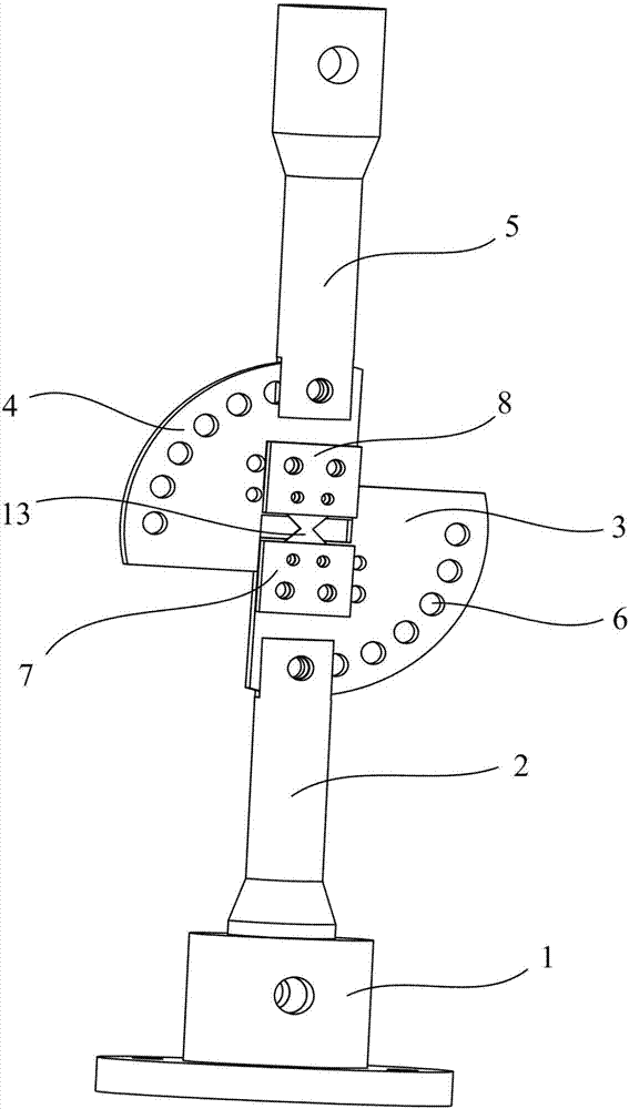
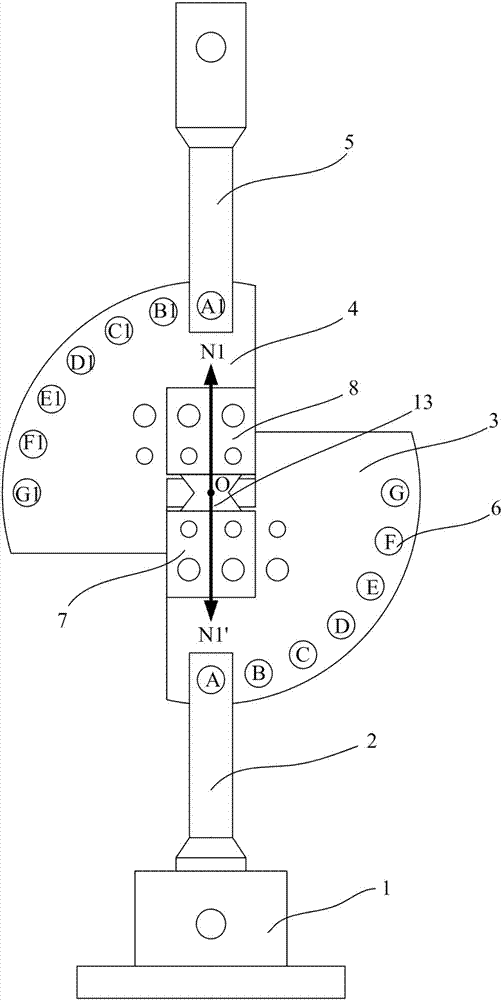
[0038] see figure 1 , in Embodiment 1 of the present invention, the clamping device includes a base 1 that can be fixedly installed on the top surface of the workbench, a lower connecting main shaft 2 connected to the top of the base 1, a lower fan-shaped flange 3 connected to the top of the lower connecting main shaft 2, The upper fan-shaped flange 4 located above the lower fan-shaped flange 3 and separated from the lower fan-shaped flange 3, and the upper connecting spindle 5 connected to the upper fan-shaped flange 4, the clamping device in the embodiment of the present invention also includes A clamping structure for clamping the test piece 13.

[0039] The clamping structure in the embodiment of the present invention includes a lower fixing block 7 for clamping one end of the test piece 13 and fixing it on the fan-shaped side of the lower fan-shaped flange 3, and a lower fixing block 7 for clamping the other end of the test piece 13 and fixing it on the upper fan-shaped f...

Embodiment 2

[0051] This embodiment is the same as Embodiment 1 except for the following features: the lower fixing block and the lower fan-shaped flange jointly clamp the opposite side of the test piece, and the upper fixing block and the upper fan-shaped flange jointly clamp The opposite sides of the holding specimen are equipped with micro-sawtooth structures.

[0052] In this embodiment, by setting the micro-sawtooth structure, the lower fixing block and the lower fan-shaped flange jointly clamp and fix one end of the test piece, and the upper fixing block and the upper fan-shaped flange jointly clamp and fix the other end of the test piece. , to prevent the specimen from loosening during the test and affect the actual test results.

Embodiment 3

[0054] This embodiment is identical with embodiment 1 except following feature:

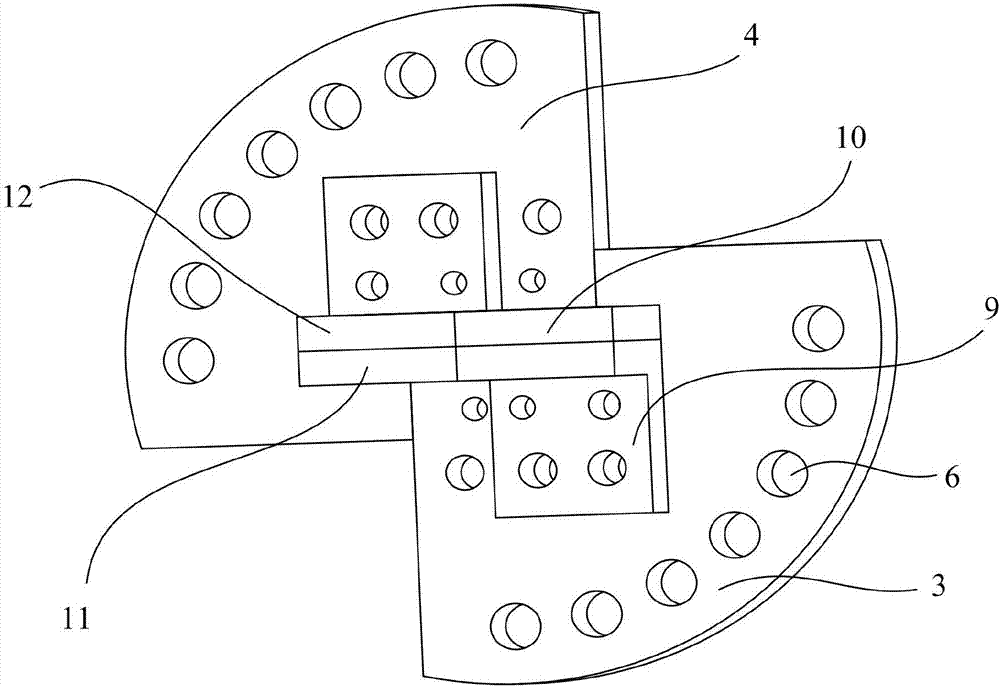
[0055] see figure 2 , the clamping structure includes a lower L-shaped fixed block 9 fixed on the fan-shaped side of the lower fan-shaped flange 3, a lower clamping block 10 connected to one end of the lower L-shaped fixed block 9 and capable of clamping one end of the test piece 13 , the upper L-shaped fixed block 12 that is fixed on the fan-shaped side of the upper fan-shaped flange 4, the upper clamping block 11 that is connected to one end of the upper L-shaped fixed block 12 and can clamp the other end of the test piece 13, the lower L The L-shaped fixing block 9 and the upper L-shaped fixing block 12 are symmetrical about the center and the side edges are flush.

[0056] see Figure 6 to Figure 8 , the lower clamping block 10 and the lower L-shaped fixing block 9 jointly clamp the opposite side of the test piece 13, and the upper clamping block 11 and the upper L-shaped fixing block 12 j...


PUM


Abstract

The invention discloses a micro mechanical property test clamping device for a material under a combined loading mode. The clamping device comprises a pedestal capable of being fixed on the top surface of a working table, a lower connection main shaft connected with the top of the pedestal, a lower fan-shaped flange disk connected with the top of the lower connection main shaft, an upper fan-shaped flange disk which is located above the lower fan-shaped flange disk and is separated from the lower fan-shaped flange disk and an upper connection main shaft connected with the upper fan-shaped flange disk, and further comprises a clamping structure for clamping a test piece. Compared with the prior art, the micro mechanical property test clamping device for the material under the combined loading mode has the advantages that by conversion of a through hole bolting position between the upper connection main shaft and the upper fan-shaped flange disk as well as a through hole bolting position between the lower connection main shaft and the lower fan-shaped flange disk, and cooperation with the test piece clamping structure with different clamping modes, a tester can conveniently complete a fracture property test of different types of materials, such as tensile failure, shear fracture, tear fracture, tensile shear combined fracture and tensile tear fracture.

Description

technical field [0001] The invention relates to the field of tooling equipment for testing mechanical properties of materials, in particular to a clamping device for testing microscopic mechanical properties of materials in a composite loading mode. Background technique [0002] In fracture mechanics, according to the relative orientation relationship between the stress and the crack surface, the fracture results can be divided into three basic types, namely type I (opening type), type II (sliding type) and type III (tearing type). ). [0003] Type I corresponds to the vertical separation of the fracture surface under the action of tensile stress, and the upper and lower surfaces of the crack surface open along the direction of the action surface, and the crack front expands forward along the crack surface. In engineering, this type of fracture includes the breaking of the plate and the longitudinal fracture of the pressure vessel. [0004] Type II corresponds to the longi...

Claims


Application Information

Patent Timeline
IPC IPC(8): G01N3/04
CPCG01N3/04G01N2203/04
Inventor 蔡权路家斌阎秋生朱奕玮
Owner GUANGDONG UNIV OF TECH
Why Eureka
Try Eureka