Rate limiting and balancing control system for dual independent camshaft phasing

a control system and camshaft technology, applied in the direction of machines/engines, output power, couplings, etc., can solve the problems of large engine oiling system demands, limited coordination of two phasers, and add engine costs, etc., to achieve smooth scheduling of intake and exhaust phaser operation, reduce engine cost, and reduce engine cost

Active Publication Date: 2008-12-23
DELPHI TECH IP LTD
View PDF3 Cites 3 Cited by
  • Summary
  • Abstract
  • Description
  • Claims
  • Application Information

AI Technical Summary

Benefits of technology

[0008]Briefly described, a control system in accordance with the invention is an extension of the single-phaser control system disclosed in U.S. Pat. No. 6,758,179 B1, the relevant disclosure of which is incorporated herein by reference. The present control system provides capability for simultaneous ratiometric scheduling of movements of dual intake and exhaust phasers relative to each other, providing smooth and consistent transitions between operating points while allowing for prioritized application of the available fluid power of the engine's oiling system. By rate-limiting the intake and exhaust phasers to different absolute rates, or as a function of the opposite phaser's control error (i.e., intake phaser rate limit is a function of the exhaust phaser position error), staging and smooth transitions can be achieved without undue computational overhead. By prioritizing rate limiting, or rate balancing of the operation of the intake and exhaust phasers or sets of phasers, lower demands are placed on the oiling system of the engine and therefore a smaller capacity oil pump may be used. Fuel economy, packaging, and cost benefits can be realized. Further, it can be advantageous for combustion and air / fuel ratio control to smoothly schedule the operation of intake and exhaust phasers. This rate balancing approach also permits the precise and repeatable operation of the cam phasers in a manner more consistent with the response characteristics of the air, fuel, and spark delivery systems of the overall engine management system, especially in areas of operation where there is surplus fluid power from the base engine oiling system which results in a cam phaser response that is too fast for the air, fuel, and spark delivery systems. Rate limiting also inherently removes bank-to-bank and car-to-car variability, as disclosed in the above-referenced patent. The system robustness enforced by the present invention upon the variation in performance characteristics of the individual elements of the cam phasing system permits relaxation of performance and / or dimensional tolerances that might otherwise drive increased piece costs and price, higher internal friction, higher reject rates in manufacturing, and / or increased rates of failure in the field in the absence of the present invention.

Problems solved by technology

A problem in operating an engine equipped with dual independent camshaft phasers (DICP) is how to coordinate their operation.
In the prior art, control methods cannot deal with both phasers simultaneously, but rather with first one phaser and then the other, in rapid alternating succession or with both moving simultaneously, resulting in limited coordination of the two phasers.
Further, large demands are placed on the oiling system of the engine during transient conditions wherein the two (or more) phasers must be actuated during the same time period.
Providing oiling system capacity to insure acceptable simultaneous actuation performance at full phasing rate adds cost to the engine, reduces fuel economy, and may result in aeration of the oil by drawing air from the engine crankcase.
Additionally, fast step changes in phase position can result in combustion and air / fuel control issues due to inconsistent movement of the cam phasers with respect to time and to each other.
Prior art hydraulically actuated cam phaser systems are susceptible to part-to-part, engine-to-engine, and even event-to-event variation that can be detrimental to combustion, air / fuel ratio control, driveability, emissions, and vehicle performance.

Method used


Image

  • Rate limiting and balancing control system for dual independent camshaft phasing
  • Rate limiting and balancing control system for dual independent camshaft phasing
  • Rate limiting and balancing control system for dual independent camshaft phasing

Examples


Embodiment Construction

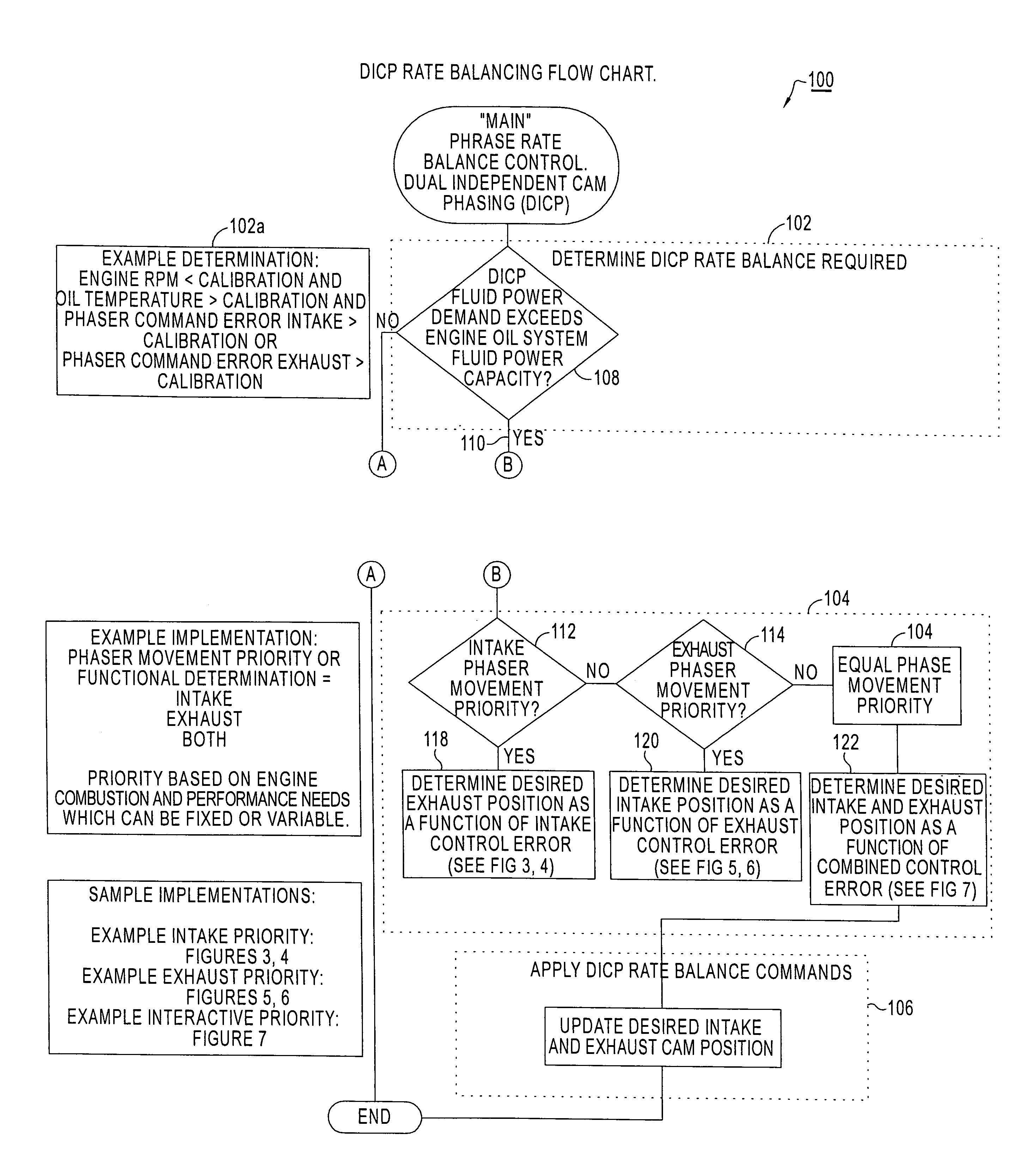
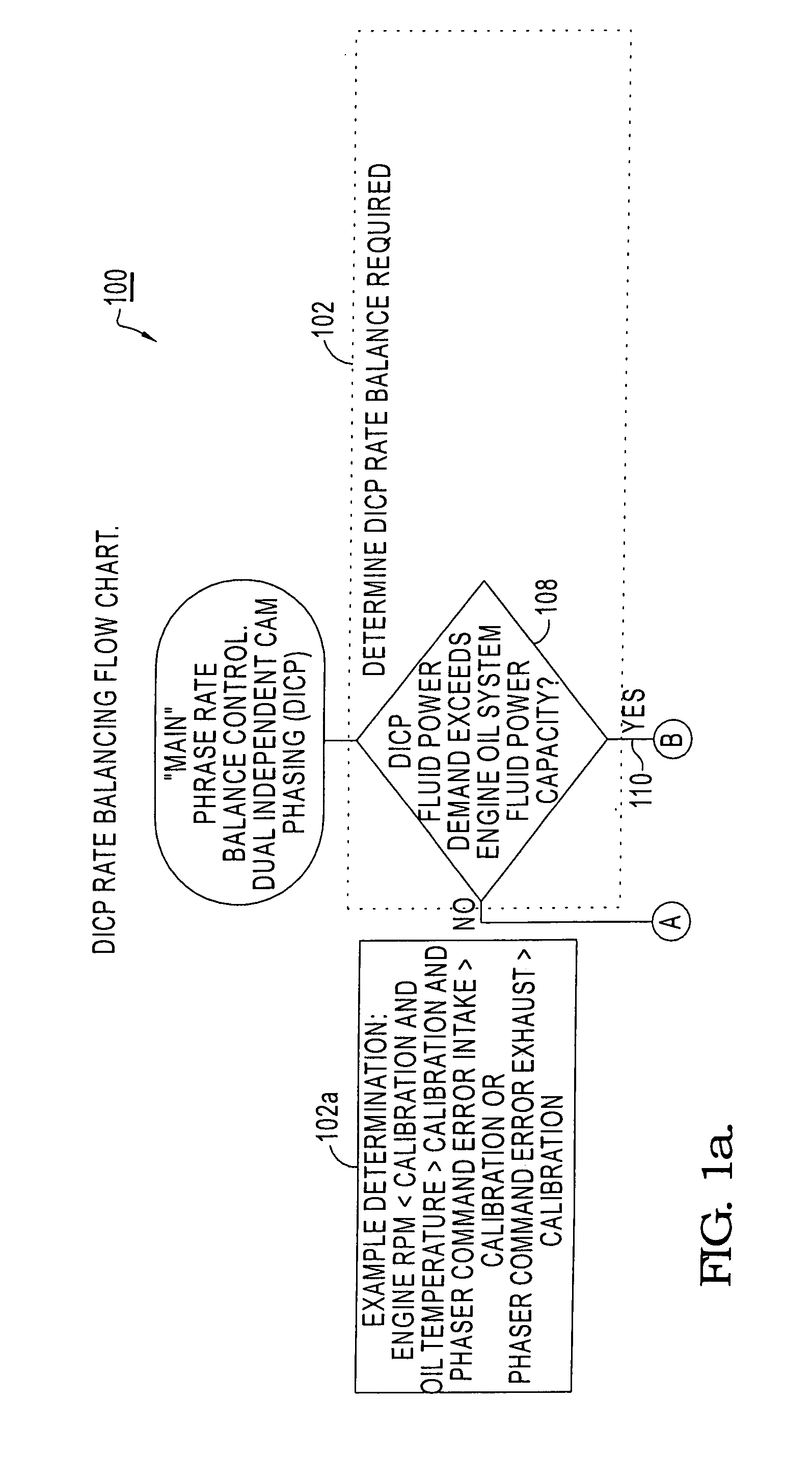
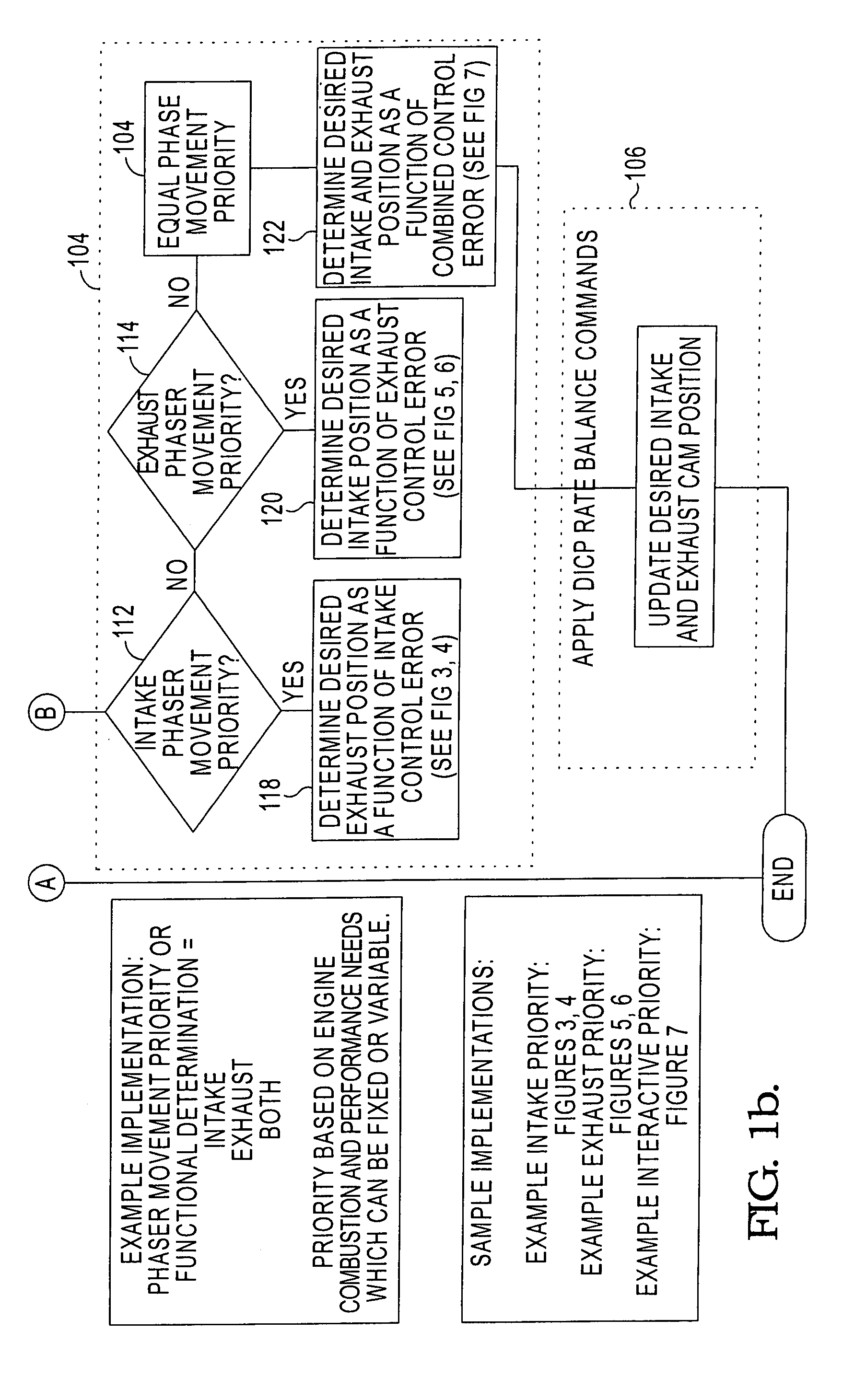
[0016]Referring now to the drawings, wherein the showings are for the purpose of illustrating an embodiment of the invention only and not for the purpose of limiting the same, FIG. 1a shows an internal combustion engine 5, controller 10, and variable cam phasing system for a dual cam engine which has been constructed in accordance with the prior art.

[0017]Engine 5 has an intake camshaft 17a that rotates around an axis and is operable to open and close each intake valve 12a corresponding to each cylinder 16 of the engine 5. The intake camshaft 17a opens each intake valve 12a relative to a top-dead center point of a piston 14 in the corresponding cylinder 16. The opening of each intake valve 12a is measured in units of degrees of camshaft rotation before the top-dead center point, and is also correlated to a position of a crankshaft 20 that is operably attached to each piston 14.

[0018]Engine 5 further has an exhaust camshaft 17b that rotates around an axis and is operable to open and ...


PUM


Abstract

A method for controlling dual independent camshaft phasers in an internal combustion engine. The method has three basic steps: a) first, determining if rate balancing between the two phasers is required; b) second, determining the optimal rate balancing commands; and c) third, applying the determined rate balancing commands to the appropriate phaser(s). In determining the rate balancing commands, there are three possible phaser options: the intake phaser requires priority; the exhaust phaser requires priority; or neither phaser requires priority. Lookup tables are stored in the engine controller for each option. When either phaser has priority, the other phaser is actuated after a delay based upon the position error of the priority phaser, generally at a lower phase rate. When neither phaser has priority, both phasers are actuated at a rate consistent with oil-delivery capabilities of the engine.

Description

TECHNICAL FIELD[0001]The present invention relates to camshaft phasers for internal combustion engines; more particularly, to methods for controlling the actions of dual camshaft phasers for intake and exhaust valves; and most particularly, to a system for controlling dual independent camshaft phasers to provide simultaneous ratiometric scheduling of the phasers' movements relative to each other.BACKGROUND OF THE INVENTION[0002]Camshaft phasers for varying the valve timing of internal combustion engines are well known. A phaser typically comprises a rotor element attached to the end of a camshaft and variably displaceable rotationally within a stator element driven by the engine crankshaft. Phasers typically are actuated by a pressure duty cycle of oil derived from the engine's main oil supply and selectively directed to chambers within the phaser to alter the phase relationship between the rotor and the stator, and hence between the camshaft and the crankshaft.[0003]Modern engines ...

Claims


Application Information

Patent Timeline
Patent Type & Authority Patents(United States)
IPC IPC(8): F01L1/34
CPCF01L1/053F01L1/185F01L1/2405F01L1/3442F01L2001/34496F01L2800/00F02D13/00Y02T10/12
Inventor MCKAY, DANIEL L.WATERS, JAMES P.
Owner DELPHI TECH IP LTD
Why Eureka
Try Eureka