
High-precision and high-stability self-capacitance detection circuit

A self-capacitance detection, high-stability technology, applied in capacitance measurement, measurement of resistance/reactance/impedance, measurement devices, etc., can solve problems such as long detection period, different detection sensitivity, and reduced detection sensitivity

Pending Publication Date: 2017-07-07
苏州芯通微电子有限公司
View PDF1 Cites 3 Cited by
  • Summary
  • Abstract
  • Description
  • Claims
  • Application Information

AI Technical Summary

Problems solved by technology

[0006] In summary, the traditional charge and discharge time detection scheme has the disadvantages of long detection period and different detection sensitivity under different parasitic capacitances; while the charge transfer scheme will increase the chip area or require additional components when the filter capacitance is large and pins, the detection sensitivity will be significantly reduced when the parasitic capacitance is larger

Method used


Image

  • High-precision and high-stability self-capacitance detection circuit
  • High-precision and high-stability self-capacitance detection circuit
  • High-precision and high-stability self-capacitance detection circuit

Examples


Embodiment Construction

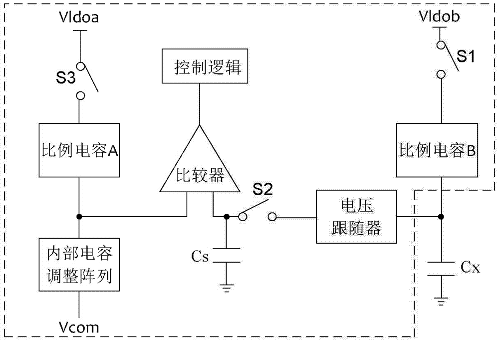
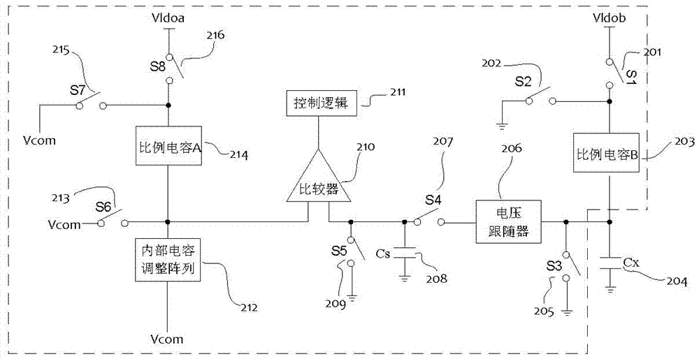
[0027] The circuit diagram of the present invention is as figure 1 As shown, the circuit includes: comparator, voltage follower, internal capacitor adjustment array, proportional capacitor A, proportional capacitor B, control logic, sampling capacitor Cs, self-capacitance Cx to be tested and switches S1, S2, S3.

[0028] In the sampling phase, the fixed voltage Vldob is applied to the terminal of the proportional capacitor B, and the proportional capacitor B and the self-capacitance Cx to be measured perform capacitive voltage division to obtain the voltage to be measured. The capacitance value of the self-capacitance Cx to be measured is converted into a voltage to be measured. The voltage follower charges the sampling capacitor Cs to the voltage to be measured, and the switch S2 between the voltage follower and the sampling capacitor Cs is turned off.

[0029] The voltage to be measured on the self-capacitance Cx to be measured is stored on the sampling capacitor Cs in the ...


PUM


Abstract

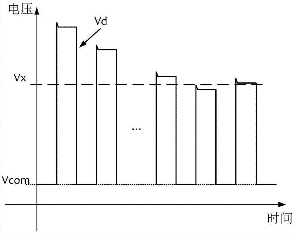
The invention provides a high-precision and high-stability self-capacitance detection circuit and relates to the field of self-capacitance detection. The circuit is characterized by obtaining voltage for representing self capacitance to be detected through a capacitive voltage divider method; then, charging a sampling capacitor to the voltage to be detected through a voltage follower, and storing the voltage of the self capacitance to be detected to the sampling capacitor in the form of charges; adjusting an internal capacitance adjustment array to enable voltage of the internal capacitance adjustment array to approximate to the voltage of the sampling capacitor in a successive approximation manner, and after finishing successive approximation, adopting the function of the capacitance of the internal capacitance adjustment array to represent the capacitance of the self capacitance to be detected. The circuit has the advantages of high precision and stability, and good sensitivity and consistency for different magnitudes of self capacitance and the like, and can improve experience of touch products and reduce development cost.

Description

technical field [0001] The present invention relates to the field of capacitance detection, and more specifically, to a method for self-capacitance detection using capacitive voltage division, which is applicable to the field of capacitive touch technology. Background technique [0002] At present, capacitive touch technology is widely used in mobile phones, tablet computers, induction cookers, refrigerators, washing machines and other products. The quality of capacitive detection technology determines the experience of capacitive touch products to a certain extent. [0003] Commonly used self-capacitance detection schemes include a detection scheme based on charge and discharge time and a detection scheme based on charge transfer. [0004] The detection scheme based on the charge and discharge time is commonly used to use the relaxation oscillator to generate a clock related to the self-capacitance to be measured, and use the clock to count the fixed time. Since sufficient...

Claims


Application Information

Patent Timeline
IPC IPC(8): G01R27/26G06F3/041G06F3/044
CPCG06F3/0416G06F3/044G01R27/2605
Inventor 赵文虎管志强邓礼君
Owner 苏州芯通微电子有限公司
Learn More