
Conveyor for pull-out circuit breakers

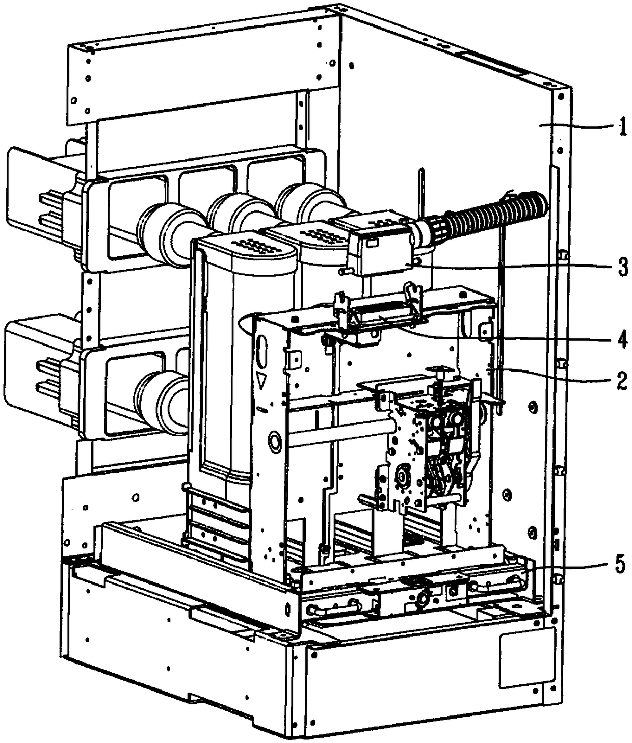
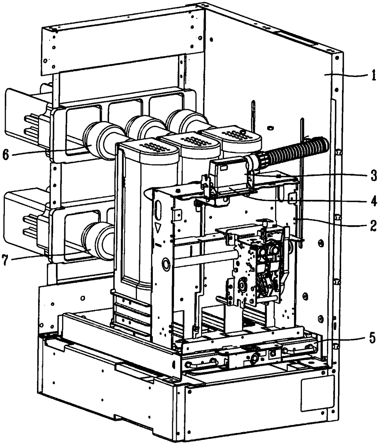
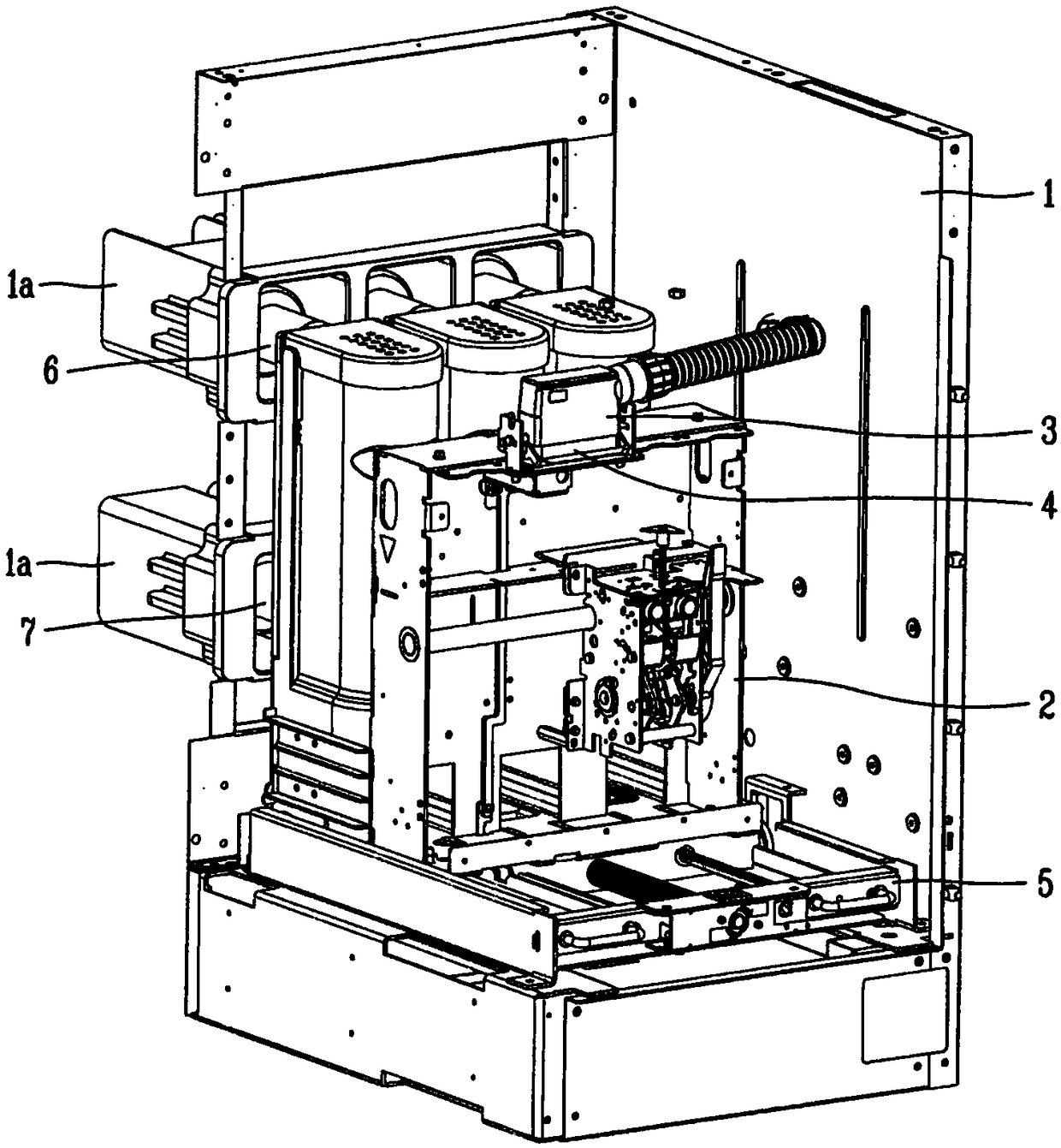
A technology of conveying device and circuit breaker, which is applied in the direction of pull-out switchgear, switchgear, building fastening devices, etc. It can solve the problems of component damage, user safety accidents, and the main body 2 cannot be pulled out from the distribution box 1. To achieve the effect of ensuring safety

Active Publication Date: 2019-01-11
LSIS CO LTD
View PDF5 Cites 0 Cited by
  • Summary
  • Abstract
  • Description
  • Claims
  • Application Information

AI Technical Summary

Problems solved by technology

[0012] At the same time, if Figure 8 As shown in FIG. 9B , in the case where only one of the sliding plates 22 or 23 is disengaged from the rail hole 1 b and the other sliding plate is held in the sliding hole 1 b due to a user's misoperation, the main body 2 cannot be removed from the power distribution rail. Case 1 is drawn out, thereby causing damage to components and safety accidents to users

Method used


Image

  • Conveyor for pull-out circuit breakers
  • Conveyor for pull-out circuit breakers
  • Conveyor for pull-out circuit breakers

Examples


Embodiment Construction

[0037] Hereinafter, preferred embodiments of a conveying device for a pull-type circuit breaker according to an embodiment of the present invention will now be described in detail with reference to the accompanying drawings.

[0038] refer to Figure 10 to Figure 13 , according to the embodiment of the present invention, the conveying device for a pull-out circuit breaker includes: a beam assembly 20 arranged on the front side of the trolley 10 and configured to push in and out the trolley 10; a body plate 21 formed with an opening A box shape on the rear side and coupled to the beam assembly 20; a pair of sliding plates 22 and 23 slidably arranged in the body plate 21; a rotating plate 40 which is rotatably arranged between the pair of sliding plates 22 and 23 And there is a stopper 44 in a protruding manner configured to limit one of the sliding plates 22 and 23 at one side thereof; One of the slide plates 22 and 23 is rotatably coupled.

[0039] refer to Figure 10 , sho...


PUM


Abstract

The present invention provides a delivery device for a draw-out circuit breaker, comprising: a beam assembly mounted on a front surface of a cart and configured to be pushed in or out of the cart; a body plate formed with an open rear side and coupled to the box shape of the beam assembly; a pair of sliding plates slidably arranged within the body plate; and a rotating plate rotatably arranged between the sliding plates, wherein the conveying device further comprises a stopper, the stopper One side of the rotating plate protrudes and is configured to restrain one sliding plate; and a connecting rod rotatably couples one end to one end of the rotating plate and rotatably couples the other end to the other end of the sliding plate.

Description

technical field [0001] The present invention relates to a conveying device of a pull-out type circuit breaker, and more particularly, relates to being capable of preventing incomplete separation of a main body of a circuit breaker by causing a left handle assembly and a right handle assembly to operate simultaneously when the main body of the circuit breaker is drawn and A pull-out circuit breaker that ensures the safety of users. Background technique [0002] Generally speaking, a circuit breaker is installed on a switchboard, which is arranged to operate or control a power station or substation, or to operate an electric motor, along with other electrical installations, and is usually housed in a switchboard fixed to the switchboard Or used in the state in the bay. [0003] In the switchboard, the base line of the circuit breaker and the load terminal are connected to the base line of the bracket, and the load terminal is used to form a service location where voltage and ...

Claims


Application Information

Patent Timeline
Patent Type & Authority Patents(China)
IPC IPC(8): H02B11/127
CPCH02B11/127H02B11/133E05C9/04H02B11/167
Inventor 金成泰
Owner LSIS CO LTD
Learn More