Trigger control method and system for reactive power adjustment event of power system

An event-triggered, power system technology, applied in reactive power adjustment/elimination/compensation, electrical components, reactive power compensation, etc. Stability and quality, the effect of reducing adjustment consumption and communication cost

Active Publication Date: 2017-07-07
ANHUI UNIVERSITY
View PDF4 Cites 6 Cited by
  • Summary
  • Abstract
  • Description
  • Claims
  • Application Information

AI Technical Summary

Problems solved by technology

However, this method has the following disadvantages: 1) It needs to establish an optimization model in advance, which is inconvenient to use; 2) It needs to calculate many intermediate variables
The disadvantage of this scheme is that the stability of the system is difficult to guarantee

Method used


Image

  • Trigger control method and system for reactive power adjustment event of power system
  • Trigger control method and system for reactive power adjustment event of power system
  • Trigger control method and system for reactive power adjustment event of power system

Examples


Embodiment Construction

[0059] The embodiments of the present invention are described in detail below. This embodiment is implemented on the premise of the technical solution of the present invention, and detailed implementation methods and specific operating procedures are provided, but the protection scope of the present invention is not limited to the following implementation example.

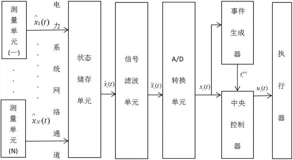
[0060] The state feedback-based power system reactive power regulation event trigger control method of the present invention includes the following steps:

[0061] 1) For the power flow status signal in the power grid i=1,2,3,...,N real-time measurement and monitoring;

[0062] 2) After filtering the real-time signal measured in 1), the power flow status signal is obtained

[0063] 3) For the power flow state signal obtained in 2) After sampling and A / D conversion, the digital signal x i (t);

[0064] 4) Calculate the digital signal x i (t) and the expected value ρ of the real-time expected grid power flo...


PUM


Abstract

The present invention discloses a trigger control method for the reactive power adjustment event of a power system. The method comprises the steps of 1) measuring and monitoring the tidal current state signal of a power grid in real time; 2) filtering the signal obtained in the step 1) to obtain a tidal current state signal; 3) processing the signal obtained in the step 2) and conducting the A / D conversion of the signal to obtain a digital signal; 4) calculating the difference between the digital signal and a real-time power grid tidal current state expected value; 5) introducing a lyapunov function, proving the stability of the system, and confirming that the state of the system can be converged to the expected value; 6) according to conclusion of the step 5), designing a method for the event trigger control of the system, and determining an event triggering condition; 7) calculating the event triggering condition of the formula 6), and triggering an event if the condition is met; 8) repeatedly executing the step 7). The invention further discloses a system adopting the above method. The method and the system have the following advantages: the power balance of the power system is ensured; the operation stability and the operation quality of the power system are improved; and the adjustment consumption and the communication cost of the system are reduced maximally.

Description

technical field [0001] The invention relates to an electric power system, and more particularly relates to a method for adjusting reactive power of an electric power system. Background technique [0002] In the power system, due to insufficient reactive power, the system voltage and power factor will be reduced, thereby damaging electrical equipment, and in severe cases, it will cause voltage collapse, disintegrate the system, and cause large-scale power outages. In addition, the reduction of power factor and voltage will also make electrical equipment not fully utilized, resulting in increased power loss and reduced efficiency, limiting the power transmission capacity of the line, affecting the safe operation of the power grid and the normal power consumption of users. [0003] In the power system, in addition to the generator as the power source of reactive power, the capacitance of the line also generates part of the reactive power. When the above two power sources canno...

Claims


Application Information

Patent Timeline
Patent Type & Authority Applications(China)
IPC IPC(8): H02J3/18
CPCY02E40/30H02J3/1885
Inventor 樊渊邱剑彬宋程张扬
Owner ANHUI UNIVERSITY
Why Eureka
Try Eureka