
Electric tractor wireless energy transmission power system and method

A technology of wireless energy transmission and power system, applied in electric vehicles, battery/battery traction, electric vehicle charging technology, etc. The problem of short pure electric running time of the whole vehicle can achieve the effect of reducing the capacity of the battery installed on the vehicle, saving the cost of the total vehicle assembly, and avoiding insufficient power

Pending Publication Date: 2019-05-24
HOITUNGINNOTEK SHENZHEN CO LTD
View PDF0 Cites 3 Cited by
  • Summary
  • Abstract
  • Description
  • Claims
  • Application Information

AI Technical Summary

Problems solved by technology

[0002] At present, when wharf enterprises use electric tractors to provide power with electric energy, the tractors will frequently start with no load, heavy loads, accelerate, stop suddenly, and wait for long-term start-up operations during wharf operations. The working conditions are diverse and complicated. Existing The tractor has the following disadvantages: 1) When the tractor starts with a heavy load, the power required by the whole vehicle is relatively high, and the power consumption of the battery is relatively large when the motor is running at high power; 2) When the tractor is fully loaded, the current is very large, requiring High-rate charging and discharging energy batteries or large-capacity batteries can meet the working conditions; high-power batteries are too expensive to be equipped with large-capacity; at the same time, large-capacity batteries occupy too much space and their own weight, resulting in low battery capacity and pure vehicle The electric running time is too short; 3) The characteristics of the port are not suitable for a large number of charging piles; 4) The actual operating conditions of the electric tractor at the terminal, the waiting time exceeds 50% of the total working time, and the waiting time exceeds 50% of the total working time. There is a 25% no-load driving ratio

Method used


Image

  • Electric tractor wireless energy transmission power system and method

Examples


Embodiment Construction

[0027] The present invention will be described in detail below in conjunction with the accompanying drawings and embodiments.

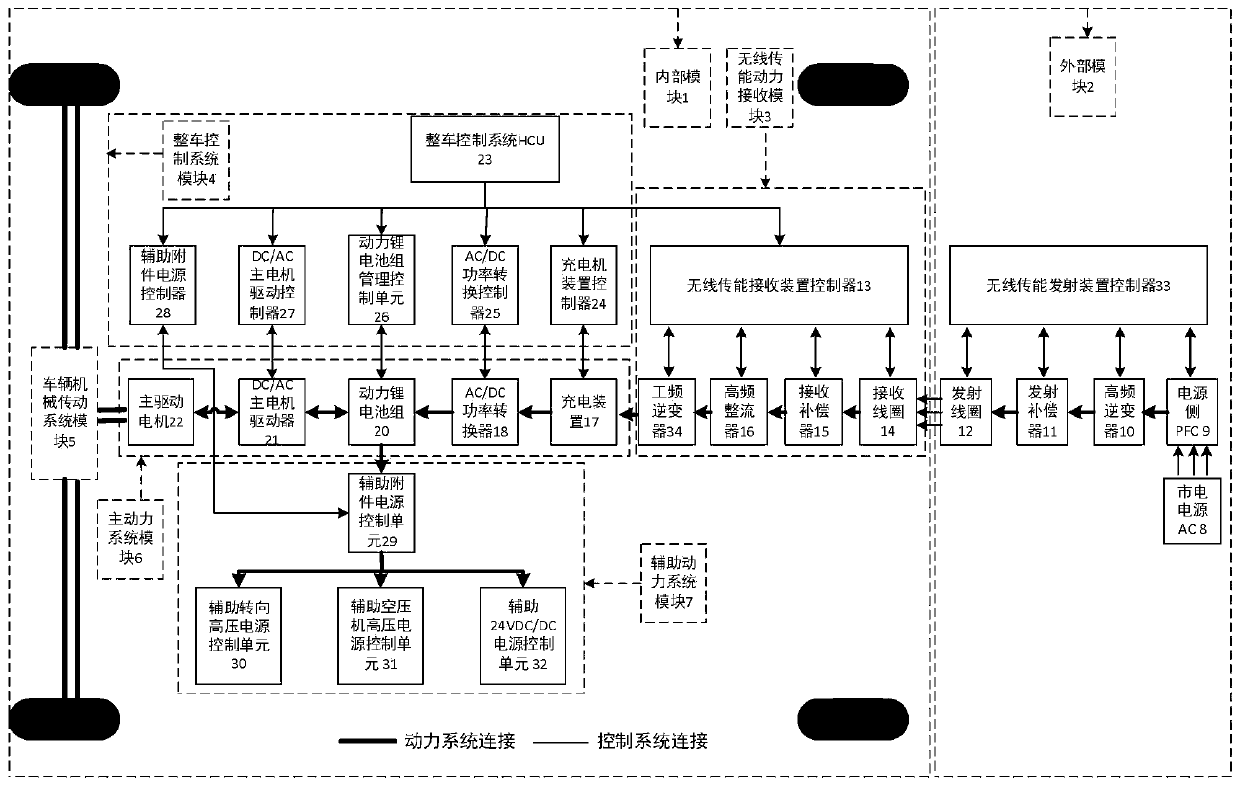
[0028] Such as figure 1 As shown, the present invention includes an internal module 1 and an external module 2; the internal module 1 of the power system of the tractor is assembled with the inside of the tractor body, and the external module 2 of the power system of the tractor is assembled on the ground where the tractor travels or within the range of energy transfer Position, the internal module 1 of the tractor power system and the external module 2 of the tractor power system transmit energy through a non-contact electromagnetic field to realize wireless power transmission.

[0029] The tractor power system internal module 1 includes a wireless energy transmission power receiving module 3, a vehicle control system module 4, a vehicle mechanical transmission system module 5, a main power system module 6, and an auxiliary power system module 7; the...


PUM


Abstract

The invention relates to an electric tractor wireless energy transmission power system and method. The electric tractor wireless energy transmission power system comprises an internal module and an external module, wherein the internal module is arranged inside a tractor body to achieve the functions of receiving alternate current energy generated by induction in an alternating magnetic field andpower supply of an overall power system; wireless energy transmission power receiving modules of the internal module are arranged at the front, in the middle or at the rear of the middle of the bottomof a tractor or at the front, in the middle or at the rear of the left and the right of the tractor; the external module is arranged in a tractor ground moving rail or within the energy transmissionrange of left and right vertical rails and achieves a function of energy transmission of the alternating magnetic field produced by an alternate current electric field through a high-frequency inverter; the internal module and the external module achieve wireless energy and power transmission through non-contact electricity transmission with electromagnetic induction, electromagnetic resonance andmicrowave.

Description

technical field [0001] The invention belongs to the field of industrial machinery and equipment, and belongs to electric power equipment, which is mainly used for short-distance horizontal transportation of goods in regional yards such as ports, and relates to a wireless energy transmission power system and method for electric tractors. Background technique [0002] At present, when wharf enterprises use electric tractors to provide power with electric energy, the tractors will frequently start with no load, heavy loads, accelerate, stop suddenly, and wait for long-term start-up operations during wharf operations. The working conditions are diverse and complicated. Existing The tractor has the following disadvantages: 1) When the tractor starts with a heavy load, the power required by the whole vehicle is relatively high, and the power consumption of the battery is relatively large when the motor is running at high power; 2) When the tractor is fully loaded, the current is ve...

Claims


Application Information

Patent Timeline
IPC IPC(8): B60L53/12B60L50/60
CPCY02T10/70Y02T10/7072Y02T90/14
Inventor 贾凯孙晓亮熊露王意斌潘划谢志文
Owner HOITUNGINNOTEK SHENZHEN CO LTD
Learn More