
Automatic dry film pressing device for PCB

A technology of PCB board and dry film, applied in the direction of lithography/pattern, pattern and lithography, transfer method, etc., can solve the problem of uneven film, achieve simple structure, avoid bubble generation and wrinkling, and stick film firmly reliable results

Active Publication Date: 2017-07-07
SUZHOU DIFEITE ELECTRONICS CO LTD
View PDF9 Cites 3 Cited by
  • Summary
  • Abstract
  • Description
  • Claims
  • Application Information

AI Technical Summary

Problems solved by technology

[0003] The technical problem to be solved by the present invention is to provide an automatic dry film pressing device for PCB boards to solve the problem of uneven film application caused by hot pressing rollers.

Method used


Image

  • Automatic dry film pressing device for PCB
  • Automatic dry film pressing device for PCB
  • Automatic dry film pressing device for PCB

Examples


Embodiment Construction

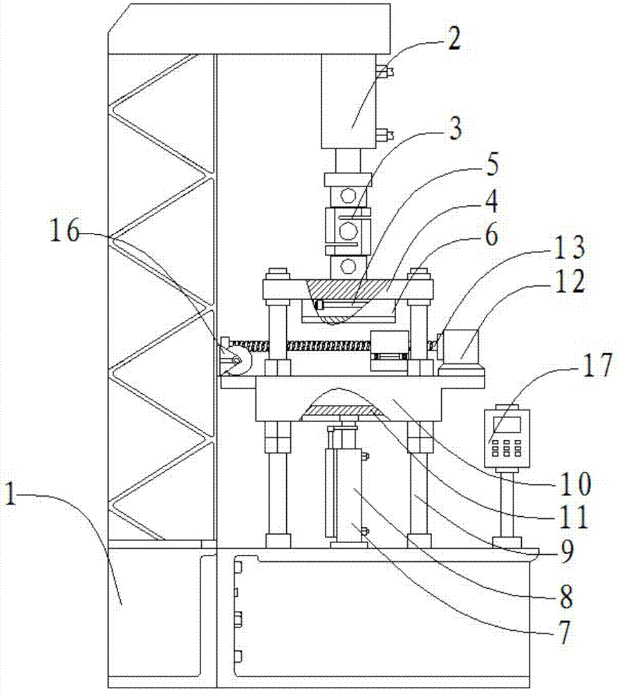
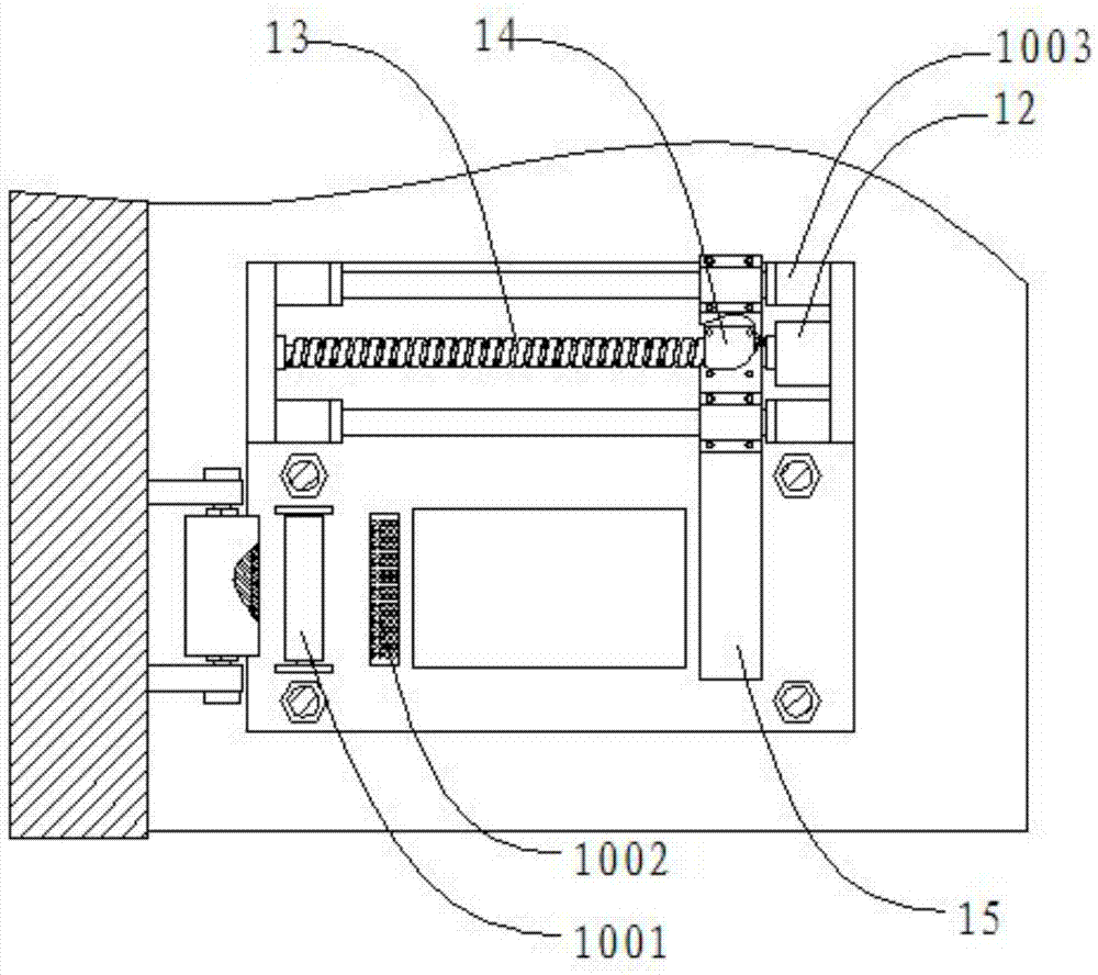
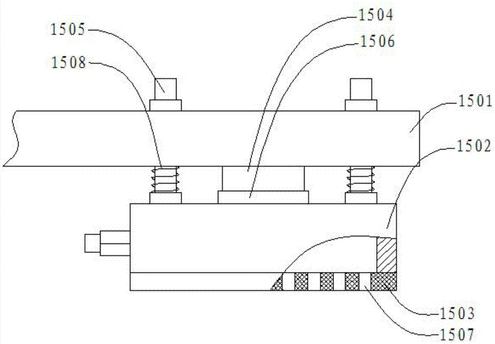
[0033] Such as figure 1 , figure 2 , image 3As shown, a PCB board automatic dry film pressing device includes a frame 1, a first cylinder 2, a pull pressure sensor 3, an upper bracket 4, a heating tube 5, a thermally conductive pressure head 6, a second cylinder 7, and a displacement sensor 8 , column 9, lower bracket 10, supporting plate 11, servo motor 12, lead screw 13, feed nut 14, film suction assembly 15, roller 16, controller 17, the first cylinder 2 is located at the upper end of the frame 1 , the first cylinder 2 is threaded with the frame 1, the tension pressure sensor 3 is located at the bottom of the first cylinder 2, the tension pressure sensor 3 is threaded with the first cylinder 2, and the upper bracket 4 is located at the lower end of the pull pressure sensor 3, the upper bracket 4 is threadedly connected with the pull pressure sensor 3, the heating tube 5 is located at the center of the bottom of the upper bracket 4, and the heating tube 5 is threaded wit...


PUM


Abstract

The invention discloses an automatic dry film pressing device for PCBs. The device comprises a frame, a first cylinder, a pull pressure sensor, an upper bracket, a heating pipe, a heat conducting pressure head, a second cylinder, a displacement sensor, columns, a lower bracket, a holding plate, a servo motor, a screw, a feed nut, a film absorbing component, a roller, and a controller. An air suction box absorbs a dry film. Then, the servo motor drives the feed nut to move leftwards through the screw, so as to drive the film absorbing component to move leftwards to right above the air suction box. After the film absorbing component absorbs the dry film under control of the controller, the film absorbing component is moved by the servo motor to a set position, and the second cylinder pushes the holding plate to move up to a set position. The first cylinder drives the upper bracket to move down, and the heat conducting pressure head presses the fry film on a PCB. The device changes the original line-contact filming mode into a surface-contact filming mode. The uniformity of filming is increased. Local bubble generation and wrinkling of a dry film on a PCB are avoided. The safety performance of PCB is improved. The labor intensity of operating personnel is reduced.

Description

technical field [0001] The invention relates to an auxiliary production device for PCB boards, in particular to an automatic drying film pressing device for PCB boards. Background technique [0002] PCB (Printed Circuit Board), the Chinese name is printed circuit board, also known as printed circuit board, is an important electronic component, a support for electronic components, and a carrier for electrical connections of electronic components. With the rapid advancement of technology, Electronic products are becoming more and more high-end, people use more and more functions such as mobile phones, computers, and televisions, and the product structure is becoming more and more miniaturized. These electronic products put forward the requirements of high quality, miniaturization and high integration for printed circuit boards. Among them, it is often necessary to paste a layer of dry film on the printed circuit board before pattern transfer to the printed circuit board, and ...

Claims


Application Information

Patent Timeline
Patent Type & Authority Applications(China)
IPC IPC(8): H05K3/06
CPCH05K3/06H05K2203/0531
Inventor 蒋建芳祝文
Owner SUZHOU DIFEITE ELECTRONICS CO LTD
Learn More