
Drilling assistant tool applied to hanging bar installation procedure

A technology for auxiliary tooling and processes, applied in the direction of manufacturing tools, metal processing equipment, maintenance and safety accessories, etc., can solve the problems of increasing the probability of safety accidents, dust entering the eyes of operators, reducing the drilling efficiency of installation holes, etc. , to achieve the effect of restoring clarity, ensuring drilling efficiency, and facilitating drilling progress

Active Publication Date: 2017-07-11
CHINA MCC5 GROUP CORP
View PDF7 Cites 5 Cited by
  • Summary
  • Abstract
  • Description
  • Claims
  • Application Information

AI Technical Summary

Problems solved by technology

However, when using a drilling rig to drill, it is necessary to manually lift the drilling rig on the scaffolding for construction. After the drill bit drills into the concrete slab, a large amount of concrete dust will be generated, and the concrete layer will spread around under the rotation of the drill bit. For the drilling accuracy of the drill bit, the operator needs to observe the drilling position and progress of the drill bit at all times, and the spreading concrete dust will seriously interfere with the operator's sight, and it is easy to cause the dust to enter the operator's eyes, which greatly reduces the installation time. The drilling efficiency of the hole is improved, and the probability of safety accidents is increased at the same time

Method used


Image

  • Drilling assistant tool applied to hanging bar installation procedure

Examples


Embodiment 1

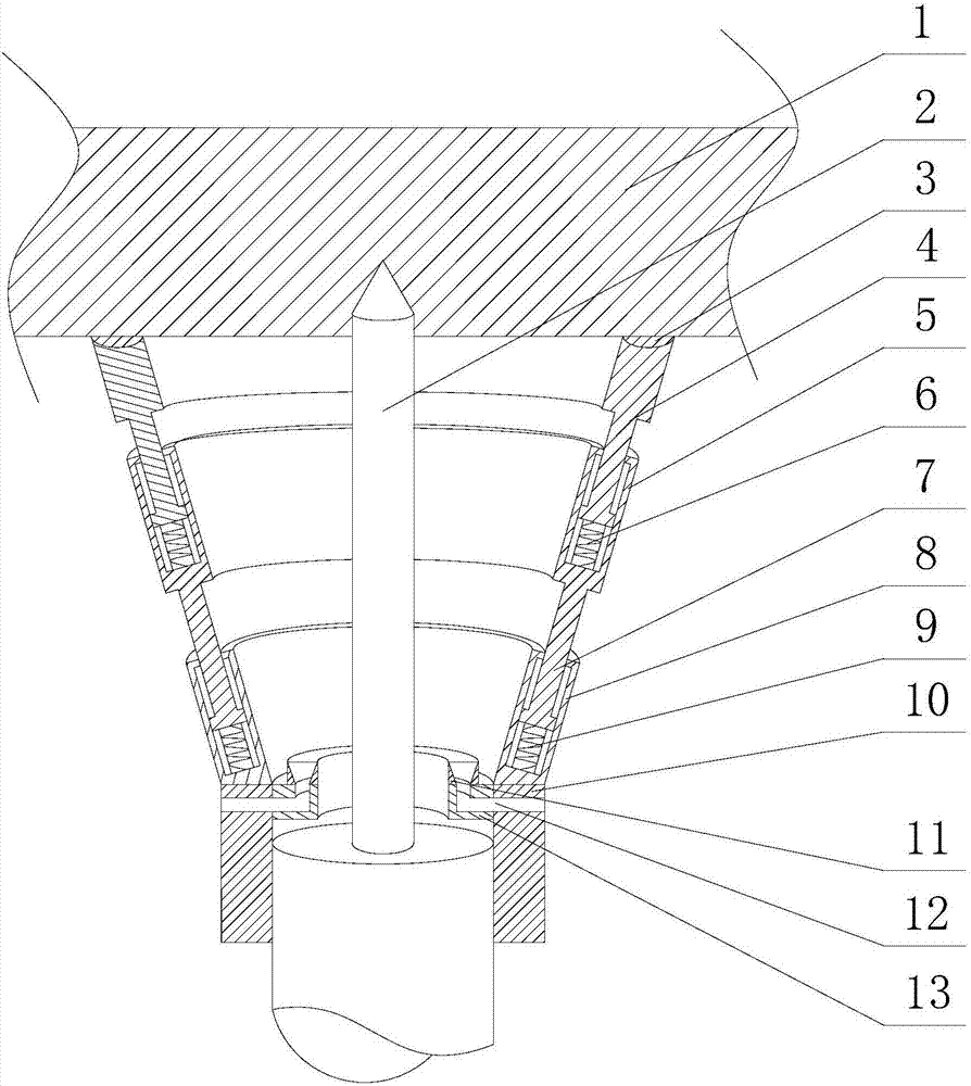
[0023] Such as figure 1 As shown, this embodiment includes a tapered tube I4, a tapered tube II5, a tapered tube III8 and a sleeve 10 with threads on the inner peripheral wall, and the small diameter section of the tapered tube III8 is connected to the upper end surface of the sleeve 10 , there is a first annular cavity on the body of the conical cylinder III8, and a plurality of springs II9 are installed on the bottom of the first annular cavity, along the circumferential direction of the small diameter section of the conical cylinder II5 on its end surface An extension section 7 is provided, and a through hole is opened on the first annular cavity. The lower section of the extension section 7 is movable through the through hole and connected with a plurality of springs II9, and is opened on the body of the conical tube II5. There is a second annular chamber, and a plurality of springs I6 are installed at the bottom of the second annular chamber, and an annular hole is opened...


PUM


Abstract

The invention discloses a drilling assistant tool applied to a hanging bar installation procedure. The drilling assistant tool comprises a conical barrel I, a conical barrel II, a conical barrel III and a sleeve, wherein the small-diameter section of the conical barrel III is connected with the upper end face of the sleeve; a first annular cavity is arranged on a main body of the conical barrel III; a plurality of springs II are arranged on the bottom part of the first annular cavity; an extending section is arranged on the end face of the conical barrel II along a circumferential direction of the small-diameter section of the conical barrel II; a through hole is formed in the first annular cavity; the lower section of the extending section movably penetrates through the through hole so as to be connected with the plurality of springs II; a second annular cavity is arranged on a main body of the conical barrel II; a plurality of springs I are arranged on the bottom part of the second annular cavity; an annular hole is formed in the second annular cavity; the small-diameter section of the conical barrel I movably penetrates through the annular hole so as to be connected with the plurality of springs I. According to the drilling assistant tool applied to the hanging bar installation procedure provided by the invention, operating personnel can conveniently observe an installation hole drilling progress in real time, concrete dust produced due to drilling is prevented from interfering sights of the operating personnel, and the occurrence of accidents caused by dust splash is prevented.

Description

technical field [0001] The invention relates to the field of building construction, in particular to an auxiliary drilling tool used in the installation process of hanging bars. Background technique [0002] The roof of a house is an important part of modern interior decoration, and it is another major part of the enclosed interior space except for the wall and the ground. The quality of the decorative effect of the ceiling directly affects the decorative effect of the entire building space. The ceiling also plays the role of absorbing and reflecting sound, installing lighting, ventilation and fire protection equipment, and its form has two types: direct type and suspended type. Suspended ceiling, also known as suspended ceiling, ceiling, concrete slab, and flat roof, is an important part of interior decoration engineering. It has the functions of heat preservation, heat insulation, sound insulation and sound absorption, and can increase indoor brightness and beauty. The ce...

Claims


Application Information

Patent Timeline
Patent Type & Authority Applications(China)
IPC IPC(8): B23Q11/00
CPCB23Q11/0071
Inventor 杨汉林高志惠田仁旭
Owner CHINA MCC5 GROUP CORP
Learn More