

Exhaust pipe conveying device placed behind pipe cutting machine
A technology for conveying devices and exhaust pipes, which is applied in the direction of conveyors, conveyor objects, transportation and packaging, etc. It can solve problems such as damage, collision of pipe end collection boxes, etc., and achieve the effect of smooth friction and easy release
- Summary
- Abstract
- Description
- Claims
- Application Information
AI Technical Summary
Problems solved by technology
Method used
Image

Examples
Embodiment 1
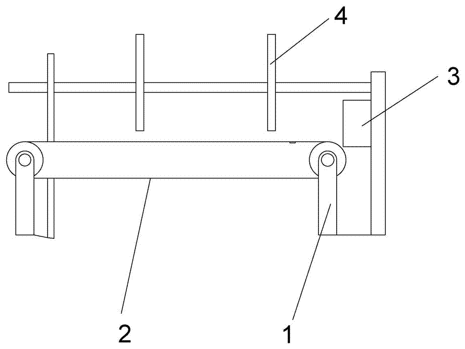
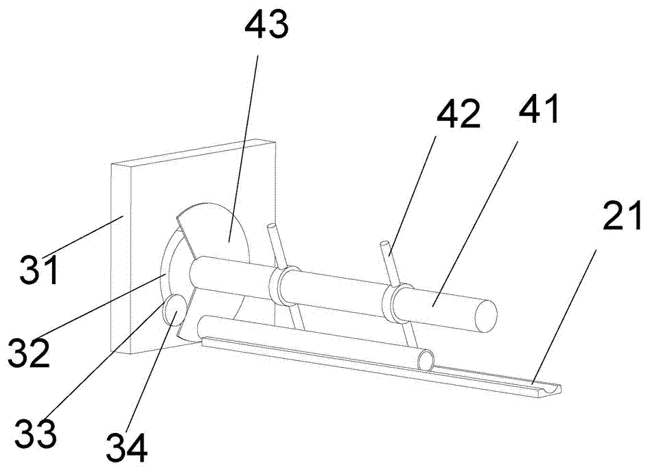
[0021] Embodiment 1: as Figure 1-3 As shown, an exhaust pipe conveying device placed behind the pipe cutter includes a frame 1, a horizontal conveyor belt 2 arranged on the frame 1, and a conveyor belt 2 at the discharge end of the conveyor belt 2. Buffered blocking device 3, a stirring device 4 provided on the frame 1 for moving the blocked exhaust pipe so that the exhaust pipe is perpendicular to the axial direction and output horizontally, and the horizontal conveyor belt 2 has Circular conveying trough 21.
[0022] In this device, the pipe cut by the pipe cutter falls into the conveying groove 21 on the horizontal conveyor belt 2, and the horizontal conveyor belt 2 drives the pipe forward, and collides with the blocking device 3 at the discharge end. During the collision, The flexible deformation of the blocking device 3 plays a buffering role on the pipe to prevent damage to the pipe. After the pipe is stabilized, the toggle device 4 moves the pipe to roll out of the de...
PUM
 Abstract
Description
Claims
Application Information