Optical fiber separation device

A technology of separating device and optical fiber, which is applied in glass manufacturing equipment, manufacturing tools, etc., to achieve the effects of simple structure, uniform width and thickness, and convenient use.

Inactive Publication Date: 2017-07-11
陈钦旺
View PDF3 Cites 1 Cited by
  • Summary
  • Abstract
  • Description
  • Claims
  • Application Information

AI Technical Summary

Problems solved by technology

[0006] The present invention aims to solve the problems described above

Method used


Image

  • Optical fiber separation device

Examples


Embodiment Construction

[0014] In order to clearly illustrate the technical features of the solution, the solution will be described below through a specific implementation mode combined with the accompanying drawings.

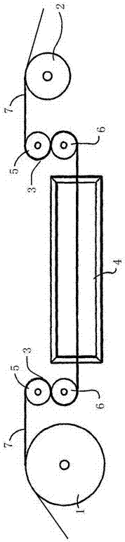
[0015] In order to achieve the above object, the present invention adopts the following technical solution: an optical fiber separation device, including a guide roller set, a separation roller set 3, a PLC control device, and a tension detection roller, and the guide roller set includes a first guide roller set 1 and a second guide roller set Two guide roller sets 2, wherein, the first guide roller set 1 is arranged before the separation roller set 3, the second guide roller set 2 is arranged after the first guide roller set 1, and the tension detection The rollers are arranged between the first guide roller group 1 and the second guide roller group 2, a tension detection roller is arranged between the first guide roller group and the separation roller group, and a tension detection ...


PUM


Abstract

An optical fiber separation device, comprising a guide roller set, a separation roller set, a PLC control device, and a tension detection roller, the guide roller set includes a first guide roller set and a second guide roller set, wherein the first guide roller set After the separating roller group, the second guiding roller group is arranged behind the first guiding roller group, and the tension detection roller is arranged between the first guiding roller group and the second guiding roller group Between, a tension detection roller is arranged between the first guide roller group and the separation roller group, and a vibration finishing device is arranged between the separation roller group. The present invention can detect the tension in the separation process of the optical fiber bundle in real time, and feed back to the PLC control device, so as to adjust the tension by controlling the linear speed of the guide motor of the guide roller group, so that the optical fiber bundle can reach the best seperate effect.

Description

technical field [0001] The invention relates to an optical fiber preparation device, in particular to an optical fiber separation device. Background technique [0002] Optical fibers used in communication systems generally include a glass core surrounded by a cladding, also made of glass with different optical properties than the core. Optical fibers are generally covered by an outer protective layer. Such optical fibers are made by drawing a thin fiber from a heated and partially molten preform consisting of a glass of suitable composition for making the core surrounded by a layer of glass of suitable composition for making the cladding. When a strand of soft molten glass is drawn from the preform, both the core glass and the cladding glass stretch. The core remains in the center and the cladding remains on the outside, resulting in a combined core and cladding structure for the finished fiber. As the fibers are pulled from the preform, cooled and solidified, the claddin...

Claims


Application Information

Patent Timeline
Patent Type & Authority Applications(China)
IPC IPC(8): C03B37/16C03B37/12
CPCC03B37/16C03B37/12
Inventor 陈钦旺
Owner 陈钦旺
Why Eureka
Try Eureka