Spraying supporting frame and a spraying device

A technology of spraying device and support frame, which is applied in the direction of spraying device, etc., can solve the problems of affecting the quality of casting high-precision centrifugal tube billet, uneven coating on the inner wall of mold cavity, and inability to ensure uniformity of spraying, so as to avoid instability , Conducive to spraying quality, simple structure effect

Active Publication Date: 2017-07-14
XINXING DUCTILE IRON PIPES CO LTD
View PDF6 Cites 2 Cited by
  • Summary
  • Abstract
  • Description
  • Claims
  • Application Information

AI Technical Summary

Problems solved by technology

[0002] Before using a horizontal centrifuge for centrifugal casting, it is necessary to spray a layer of coating on the inner wall of the mold cavity. The existing technology is to put the spray gun on the head of the push rod and extend the spray gun to the mold cavity by the push rod. The other end of the interior is then sprayed during the process of pulling the push rod back; during the process, the front end of the push rod naturally droops due to gravity, and with the retraction of the push rod, the head of the drooping push rod gradually returns to the required height, so that During the spraying process, the spray gun forms a process from low to high during the movement of the inner wall of the mold cavity, which makes the coating on the inner wall of the mold cavity uneven and affects the quality of the cast high-precision centrifugal tube blank
[0003] In the Chinese Utility Model Patent (Application No. 201420572994.X), a height-adjustable pipeline inner wall spraying equipment is disclosed. The spraying pipe is supported by a height adjustment device. The walking device, its application range is the spraying operation in which the pipeline to be sprayed does not rotate by itself, and the walking device travels along the axial direction of the pipeline; if the spraying operation is carried out while the pipeline to be sprayed rotates at a constant speed, this device cannot be applied, because in In a pipeline that rotates at a constant speed, the walking device is prone to shift under the drive of the inner wall of the pipeline, so the spraying distance of the spray gun is always changing, and the uniformity of spraying cannot be guaranteed

Method used


Image

  • Spraying supporting frame and a spraying device
  • Spraying supporting frame and a spraying device
  • Spraying supporting frame and a spraying device

Examples


Embodiment Construction

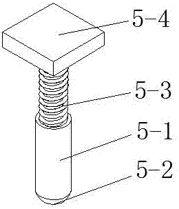
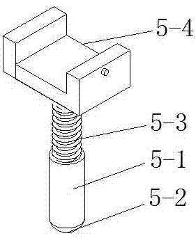
[0029] Such as figure 1 , figure 2 As shown, the spraying support frame includes a pole 5-1, which is provided with a height adjustment device on the pole 5-1, and a universal ball 5-2 is provided at the bottom of the pole 5-1; The threaded sleeve on the -1 and the telescopic rod 5-3 with external thread matched with the threaded sleeve.

[0030] Such as figure 1 , figure 2 As shown, the support frame also includes a support 5-4 arranged on the top of the pole 5-1, and the pole 5-1 is vertically fixed on the support 5-4; the top surface of the support 5-4 can be a plane structure, or It can be a groove structure. If the top of the support 5-4 is a plane structure, it is used to insert the push rod 1 into the groove that matches the plane structure; if the top of the support 5-4 is a groove structure, it is used to use The push rod 1 is inserted so that the support frame is fixed on the push rod 1.

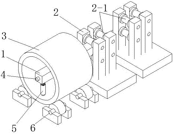
[0031] Such as image 3 , Figure 4 As shown, the spraying device for...


PUM


Abstract

The invention discloses a spraying supporting frame and a spraying device and belongs to the technical field of coating spraying. The supporting frame comprises a supporting rod; a height adjusting device is arranged on the supporting rod; and a universal ball is arranged at the bottom of the supporting rod. According to the supporting frame, by arranging the universal ball, the requirement of axial constant speed walking of the supporting frame on the inner wall of a mould cavity which rotates with the constant speed is met; by arranging the height adjusting device, the requirement that a supporting pushing rod reaches the level is met; and meanwhile the supporting frame is simple in structure, can be quickly mounted at the front end of the pushing rod and prone to disassembling, and does not affect the production rhythm.

Description

technical field [0001] The invention relates to the technical field of paint spraying, in particular to the spraying of the inner wall of a mold cavity of a horizontal centrifuge. Background technique [0002] Before using a horizontal centrifuge for centrifugal casting, it is necessary to spray a layer of coating on the inner wall of the mold cavity. The existing technology is to put the spray gun on the head of the push rod and extend the spray gun to the mold cavity by the push rod. The other end of the interior is then sprayed during the process of pulling the push rod back; during the process, the front end of the push rod naturally droops due to gravity, and with the retraction of the push rod, the head of the drooping push rod gradually returns to the required height, so that During the spraying process, the spray gun forms a process from low to high during the movement of the inner wall of the mold cavity, which makes the coating on the inner wall of the mold cavity ...

Claims


Application Information

Patent Timeline
Patent Type & Authority Applications(China)
IPC IPC(8): B05B13/06B05B15/06B05B13/04B05B13/02
Inventor 苗利明马平原
Owner XINXING DUCTILE IRON PIPES CO LTD
Why Eureka
Try Eureka