Shot blaster blades and impeller body assembly of shot blaster

A shot blasting machine and blade technology, used in impellers, rotor blades, metal processing equipment, etc., can solve the problems of shortening the service life of blades, increasing the cost of use, increasing energy consumption, etc., reducing the turbulent dissipation rate and weakening the burst strength. , the effect of improving work efficiency

Pending Publication Date: 2017-07-14
UNIV OF JINAN
View PDF7 Cites 5 Cited by
  • Summary
  • Abstract
  • Description
  • Claims
  • Application Information

AI Technical Summary

Problems solved by technology

[0003] In the existing technology, shot blasting machines are divided into wet shot blasting and dry shot blasting. The dry shot blasting machine has poor phosphorus removal effect. During the shot blasting process, it will generate large noise and dust, which will adhere to the workpiece and affect the surface of the workpiece. quality, and it will also increase the temperature of the metal strip, causing deformation of the workpiece, and the dry shot blasting machine has a short service life, serious equipment wear, pollutes the environment, and endangers the physical and mental health of the operator. The parts are processed, while the wet shot blasting machine does not have these problems
However, there are also many problems in the wet shot blasting technology. For example, the working environment medium of the blade in the wet shot blasting changes from air to liquid, and the viscous resistance of the liquid is obviously greater than that of the air. The large resistance will not only increase the wear of the blade , shorten the service life of the blade, and also reduce the speed of the shot blasting device in the wet shot blasting, which greatly reduces the work efficiency, increases energy consumption, and increases the cost of use

Method used


Image

  • Shot blaster blades and impeller body assembly of shot blaster
  • Shot blaster blades and impeller body assembly of shot blaster
  • Shot blaster blades and impeller body assembly of shot blaster

Examples


Embodiment Construction

[0028] In order to make the object, technical solution and advantages of the present invention clearer, the present invention will be further described in detail below in conjunction with the accompanying drawings.

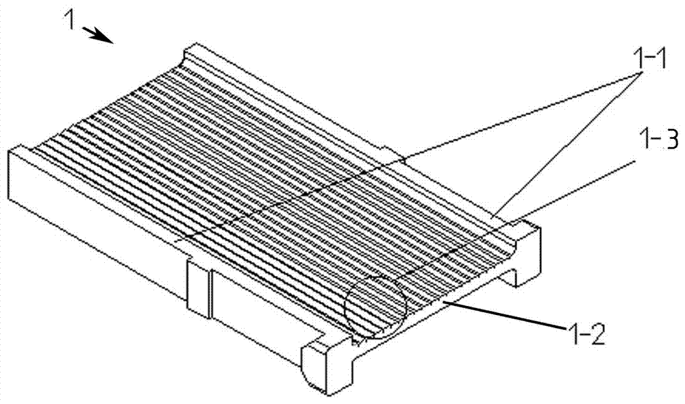
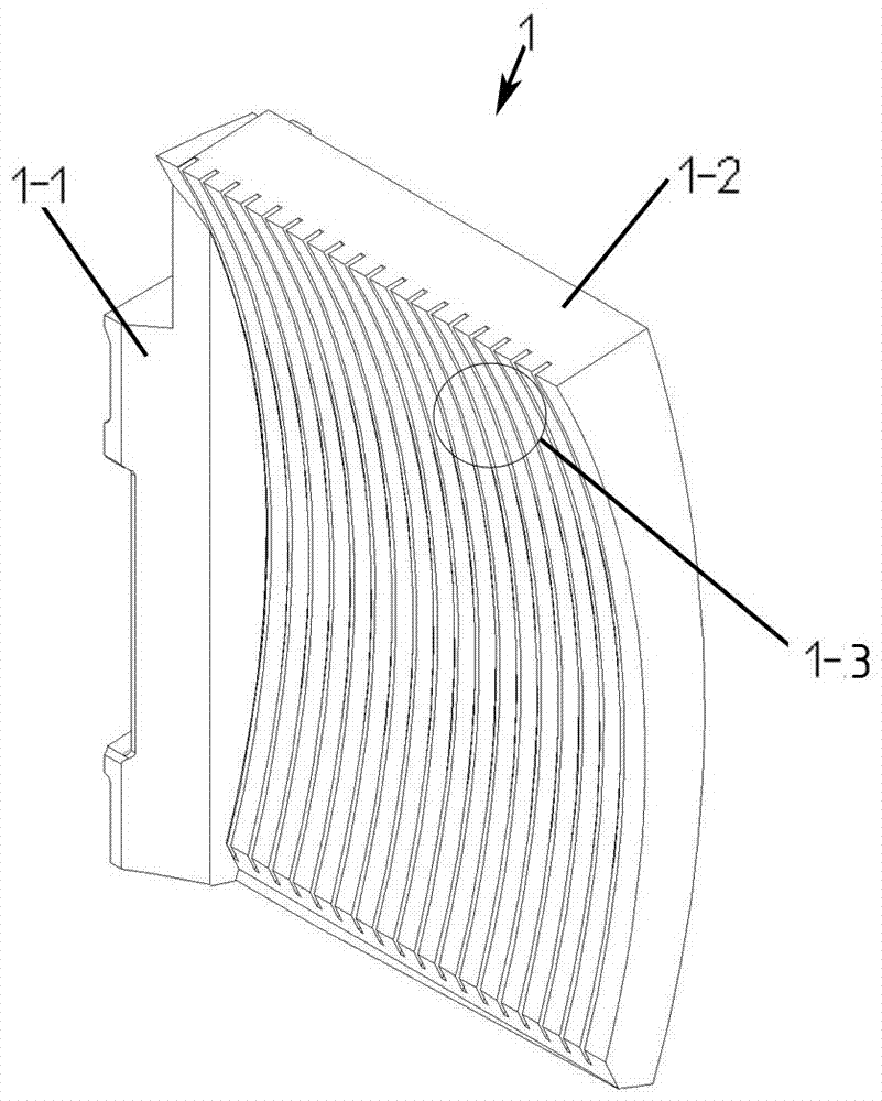
[0029] Such as figure 1 , 2 , 9, a blasting machine blade 1, including a base 1-1 and a sheet 1-2, the sheet 1-2 is provided with a surface texture 1-3, the sheet 1-2 Both the upper surface and the lower surface are provided with a surface texture 1-3, the direction of the surface texture 1-3 is along the direction of projectile movement, and the blades of the blasting machine are curved blades or plane straight blades, and the plane straight blades are The inclination angle at the inlet of the water pill mixture is α, and the inclination angle α is 10°-22°.

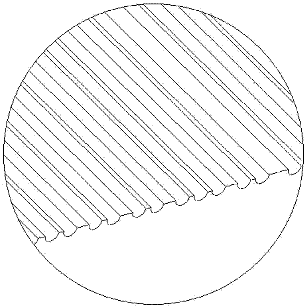
[0030] Such as image 3 , 4 As shown, the surface texture is a U-shaped groove, the groove width of the U-shaped groove is W, the long distance of the U-shaped groove is L, and the short distance of the ...


PUM


Abstract

The invention discloses shot blaster blades and an impeller body assembly of a shot blaster and belongs to the technical field of shot blasters. The impeller body assembly comprises an impeller body, and the impeller body comprises an impeller plate. The impeller plate is provided with clamping grooves. The shot blaster blades are connected to the clamping grooves in a clamped mode. Each shot blaster blade comprises a base and a blade body, and the blade body is provided with a surface texture. According to the shot blaster blades and the impeller body assembly of the shot blaster, viscosity resistance can be reduced, abrasion to the blades is reduced, the blasting speed of the shot blaster is increased, the work efficiency is greatly improved, energy consumption is reduced, and the use cost is reduced.

Description

technical field [0001] The invention relates to the technical field of blasting machines, in particular to a blasting machine blade and an impeller body assembly. Background technique [0002] Shot blasting is also the name of a mechanical surface treatment process. The principle of shot blasting is to use a motor to drive the impeller body to rotate, and rely on the centrifugal force to throw the projectiles to the surface of the workpiece to make the surface of the workpiece reach a certain roughness. The workpiece becomes beautiful, or the welding tensile stress of the workpiece is changed to compressive stress, so as to improve the service life of the workpiece. As the core component of the shot blasting machine, the working efficiency of the shot blasting machine directly determines the working efficiency of the shot blasting machine, and the shot blasting machine blade affects the efficiency of the shot blasting machine. [0003] In the existing technology, shot blast...

Claims


Application Information

Patent Timeline
Patent Type & Authority Applications(China)
IPC IPC(8): B24C5/06
CPCB24C5/062
Inventor 颜新宇王守仁王立虎夏佃秀王成王鑫松薛传艺张晓东
Owner UNIV OF JINAN
Why Eureka
Try Eureka