Self-inspection system of 3D printer

A self-inspection system and printer technology, applied in 3D object support structure, additive manufacturing, processing data acquisition/processing, etc., can solve the problems that restrict the development of 3D printer industry, the requirements for debugging and operation are very harsh, and there is not enough attention. Achieve the effect of eliminating technical problems and bad effects, improving the printing success rate, and improving the printing effect

Inactive Publication Date: 2017-07-14
胡达广
View PDF4 Cites 3 Cited by
  • Summary
  • Abstract
  • Description
  • Claims
  • Application Information

AI Technical Summary

Problems solved by technology

Therefore, when there is a deviation between the hot plate and the positioning reference, it will seriously affect the printing effect and success rate. This technical inconsistency is a major technical defect of the existing 3D printing technology; on the other hand, the 3D printer uses Mechanical positioning system, at the same time, it has very strict requirements on the debugging and operation of the mechanical positioning system. The distance between the hot stage and the nozzle and the non-parallelism between the hot stage positioning system and the reference plane must ensure that the difference is less than tens of microns. These requirements are absolutely It is a great difficulty for most users who do not have mechanical expertise and professional tools; Due to the tossing of factors, the benchmark of the positioning system of the 3D printer or the heating stage will change to varying degrees, and these changes will inevitably cause the above problems
At present, the 3D printers under the existing technology do not pay enough attention to this aspect, so that these factors seriously restrict the development of the 3D printer industry.

Method used


Image

  • Self-inspection system of 3D printer

Examples


Embodiment Construction

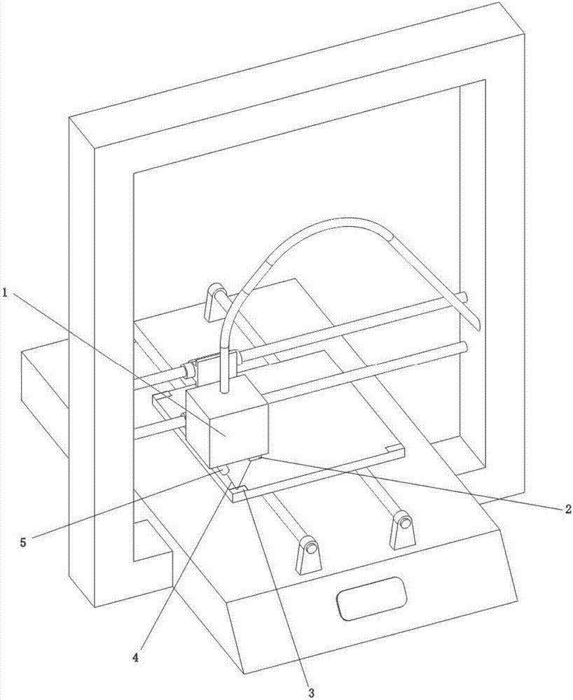
[0010] The 3D printed model or workpiece is finally generated on the hot stage, but the 3D printed data in the prior art is based on the starting point of the coordinates of the positioning system. In this way, when there is a deviation between the hot stage and the benchmark of the positioning system, it will inevitably affect the printing accuracy of the model or workpiece, and in severe cases, the printing will not be successful. In order to enable the 3D printer to automatically adapt to the deviation or change of the heating table and / or positioning system, the present invention adopts the following technical measures: a laser emitting head and a photoelectric receiving array are installed on the printing head, and a minimum of three different positions on the heating table Process or install the reflective mirror surface, the laser beam is not perpendicular to the reflective mirror surface, the photoelectric receiving array is connected to the computer, and the signals ou...


PUM


Abstract

A self-inspection system for a 3D printer, the invention is a technical field of the 3D printer. In order to enable 3D printing to be carried out based on the actual situation of the hot table, the present invention installs a laser emitting head and a photoelectric receiving array on the print head, processes or installs a reflective mirror on the hot table, and the laser beam is not perpendicular to the reflective mirror and is transmitted by The reflective mirror surface is reflected to the photoelectric receiving array for reception, and the computer drives the printing head, laser emitting head and photoelectric receiving array through the positioning system to detect the distance of the smallest three reflective mirrors in different places on the heating table, and the computer uses the detection results of the photoelectric receiving array as the basis Recalculate the printing data, so that the printing data can be 3D printed based on the actual situation of the heating table; All technical problems and adverse effects caused by the deviation between the heating stage plane and the positioning system in the prior art are eliminated.

Description

technical field [0001] The present invention is a technical field of 3D printers. Background technique [0002] 3D printing can make the virtual image on the computer screen magically become the real material world. At present, the fused deposition method (FDM) is widely used in 3D printing technology. The cost of this kind of 3D printing machine and consumables is relatively low, but it is based on physical mechanical positioning and fusion deposition printing technology, so it is a A printing technology with low printing accuracy. However, due to its low adult size, it has strong vitality. Its working principle is to rely on the nozzle to spin the wire, and cooperate with the mobile positioning of the mechanical positioning system to realize hot-melt accumulation printing. [0003] People who have used fused accumulation 3D printing machines will complain about the difficulty of operation and low printing success. One of the reasons is that this printing method has hig...

Claims


Application Information

Patent Timeline
Patent Type & Authority Applications(China)
IPC IPC(8): B29C64/118B29C64/393B29C64/20B33Y30/00B33Y50/02
CPCB33Y30/00B33Y50/02
Inventor 胡达广
Owner 胡达广
Why Eureka
Try Eureka