Fixed-point unloading mechanism

An unloading mechanism and fixed-point technology, applied in the field of fixed-point unloading mechanism and material transportation and unloading, can solve the problems of complex vehicle structure, high energy consumption, high labor intensity, etc., and achieve the expansion of the scope of application, low cost, and high unloading efficiency. Effect

Pending Publication Date: 2017-07-14
高伟
View PDF0 Cites 4 Cited by
  • Summary
  • Abstract
  • Description
  • Claims
  • Application Information

AI Technical Summary

Problems solved by technology

[0002] At present, the transport vehicles in the domestic market need people to unload the vehicles, which is very labor-intensive, such as grain transport vehicles or cotton transport vehicles. The relatively high-end grain transport vehicles are mostly one-way rollover grain unloading mechanisms. The vehicle structure Very complex, high cost, and consumes a lot of energy

Method used


Image

  • Fixed-point unloading mechanism
  • Fixed-point unloading mechanism
  • Fixed-point unloading mechanism

Examples


Embodiment 1

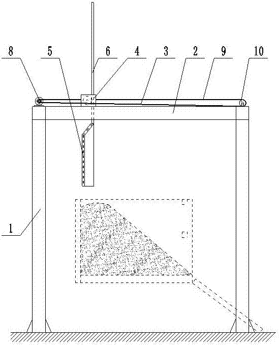
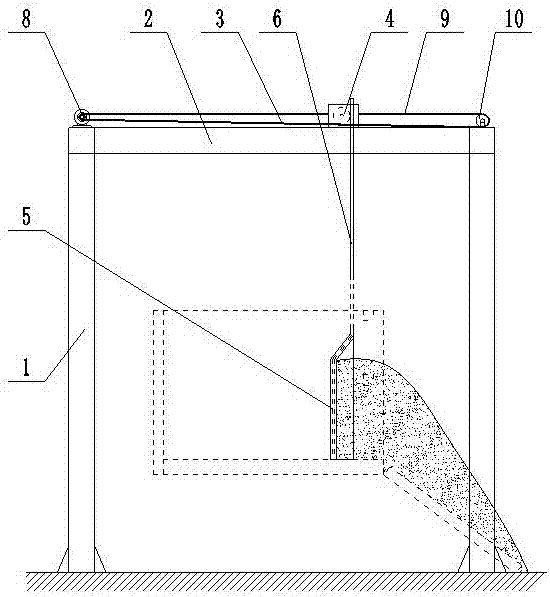
[0035] like figure 1 As shown, the fixed-point unloading mechanism includes a frame body 1, a beam 2, a horizontal transmission mechanism 3, a vertical transmission mechanism 4, a discharge plate 5 and a controller. The frame body 1 is fixed on the ground, and the beam 2 is fixed on the frame body. 1. The horizontal transmission mechanism 3 is installed on the beam 2. The vertical transmission mechanism 4 is movably installed on the beam 2 and realizes the lateral movement on the beam 2 through the horizontal transmission mechanism 3. The vertical transmission mechanism 4 and the discharge plate The upper connecting rod 6 of 5 is connected to realize the up and down movement of the unloading plate 5, and the controller controls the operation of the horizontal transmission mechanism 3 and the vertical transmission mechanism 4.

[0036] The vertical transmission mechanism 4 includes a transmission box 11, a vertical motor 12, a first gear 13 and a first rack 14, the transmission...

Embodiment 2

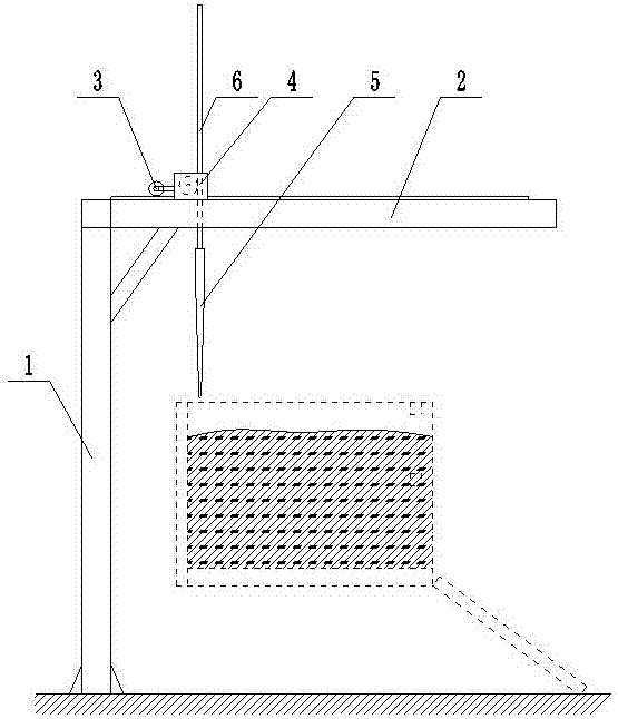
[0045] like image 3 As shown, the fixed-point unloading mechanism includes a frame body 1, a beam 2, a horizontal transmission mechanism 3, a vertical transmission mechanism 4, a discharge plate 5 and a controller. The frame body 1 is fixed on the ground, and the beam 2 is fixed on the frame body. 1. The horizontal transmission mechanism 3 is installed on the beam 2. The vertical transmission mechanism 4 is movably installed on the beam 2 and realizes the lateral movement on the beam 2 through the horizontal transmission mechanism 3. The vertical transmission mechanism 4 and the discharge plate The upper connecting rod 6 of 5 is connected to realize the up and down movement of the unloading plate 5, and the controller controls the operation of the horizontal transmission mechanism 3 and the vertical transmission mechanism 4.

[0046] The vertical transmission mechanism 4 includes a transmission box 11, a vertical motor 12, a first gear 13 and a first rack 14, the transmission...


PUM


Abstract

The fixed-point unloading mechanism of the present invention belongs to the technical field of material transportation; the technical problem to be solved is: to provide a fixed-point unloading mechanism, which is convenient and flexible to use, has low cost, reduces the labor intensity of workers, and improves the efficiency of unloading; the adopted technology The scheme is: a fixed-point unloading mechanism, including a frame body, a beam, a horizontal transmission mechanism, a vertical transmission mechanism, a discharge plate and a controller. The frame body is fixed on the ground, and the beam is fixed on the upper part of the frame body. The transmission mechanism, the vertical transmission mechanism is movably installed on the beam and realizes the lateral movement on the beam through the horizontal transmission mechanism. The vertical transmission mechanism is connected with the upper connecting rod of the discharge plate to realize the up and down movement of the discharge plate. The controller controls the operation of the horizontal transmission mechanism and the vertical transmission mechanism; the invention is mainly used for transporting and unloading materials such as grain and cotton.

Description

technical field [0001] The fixed-point unloading mechanism of the invention belongs to the technical field of material transportation, and specifically relates to the transportation and unloading of materials such as grain and cotton. Background technique [0002] At present, the transport vehicles in the domestic market need people to unload the vehicles, which is very labor-intensive, such as grain transport vehicles or cotton transport vehicles. The relatively high-end grain transport vehicles are mostly one-way rollover grain unloading mechanisms. The vehicle structure Very complex, high cost, great energy consumption. Contents of the invention [0003] The invention overcomes the deficiencies in the prior art, and the technical problem to be solved is: to provide a fixed-point unloading mechanism, which is convenient and flexible to use, has low cost, reduces labor intensity of workers, and improves unloading efficiency. [0004] In order to solve the above-mentioned...

Claims


Application Information

Patent Timeline
Patent Type & Authority Applications(China)
IPC IPC(8): B65G67/26
CPCB65G67/26
Inventor 高伟
Owner 高伟
Why Eureka
Try Eureka