A top pressure type elevator counterweight pressing piece

A counterweight, top-pressing technology, applied in the direction of lifting equipment, elevators, transportation and packaging in mines, can solve the problems of the pressing action to be improved, the pressing parts are easy to loosen, the strength is reduced, etc., to improve friction. performance, prevent mutual sliding, easy to adjust the size of the effect

Inactive Publication Date: 2019-01-04
朱爱民
View PDF6 Cites 0 Cited by
  • Summary
  • Abstract
  • Description
  • Claims
  • Application Information

AI Technical Summary

Problems solved by technology

This compaction scheme has the following problems: 1. The structure is complex and the production efficiency is low; 2. A series of holes are opened on the straight beam, and the processing procedures are numerous and the efficiency is low; 3. After the holes are opened on the vertical beam, the strength is reduced and the elevator runs stably The performance and safety are reduced, and the wear degree of the CNC mold is increased; 4. All the bolts need to be unscrewed for disassembly and up and down adjustment of the U-shaped compression structure, which is not convenient enough
The counterweight pressing device provided by the technical solution disclosed in the above utility model has a simple structure and remarkable pressing effect, which overcomes the need to set a plurality of holes on the vertical beam in order to press the counterweight in the prior art, which causes the vertical beam to be damaged. Disadvantages of reduced strength
However, in the technical solution provided by this utility model, the pressing part is easy to loosen during operation, so its pressing effect needs to be improved

Method used


Image

  • A top pressure type elevator counterweight pressing piece
  • A top pressure type elevator counterweight pressing piece
  • A top pressure type elevator counterweight pressing piece

Examples


Embodiment 1

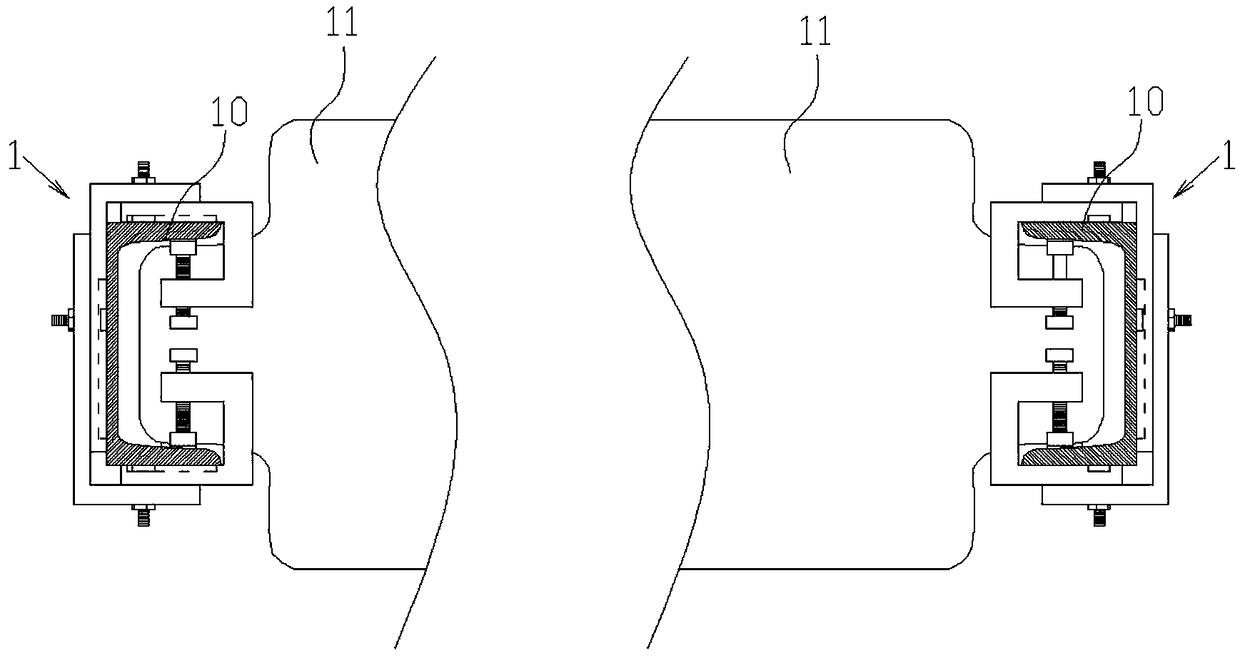
[0029] figure 1 and figure 2 A top-pressure elevator counterweight pressing piece provided according to the first embodiment of the present invention is schematically shown.

[0030] like figure 1 and figure 2 As shown, a top-pressing elevator counterweight block pressing piece disclosed in the present invention includes a pressing piece body 1 that clamps the vertical beam 10 of the counterweight frame. like figure 1 As shown, the counterweight upright beam 10 includes the left counterweight upright beam and the right counterweight upright beam that are arranged oppositely, and the cross-sections of the left counterweight upright beam and the right counterweight upright beam are in a "U" shape, and the left counterweight upright beam is in a "U" shape. The openings of the upright beam of the counterweight frame and the upright beam of the right counterweight frame are arranged oppositely, wherein the elevator counterweight block 11 is vertically stacked between the upri...

Embodiment 2

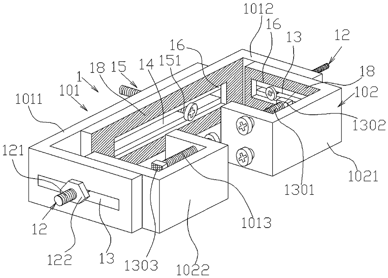
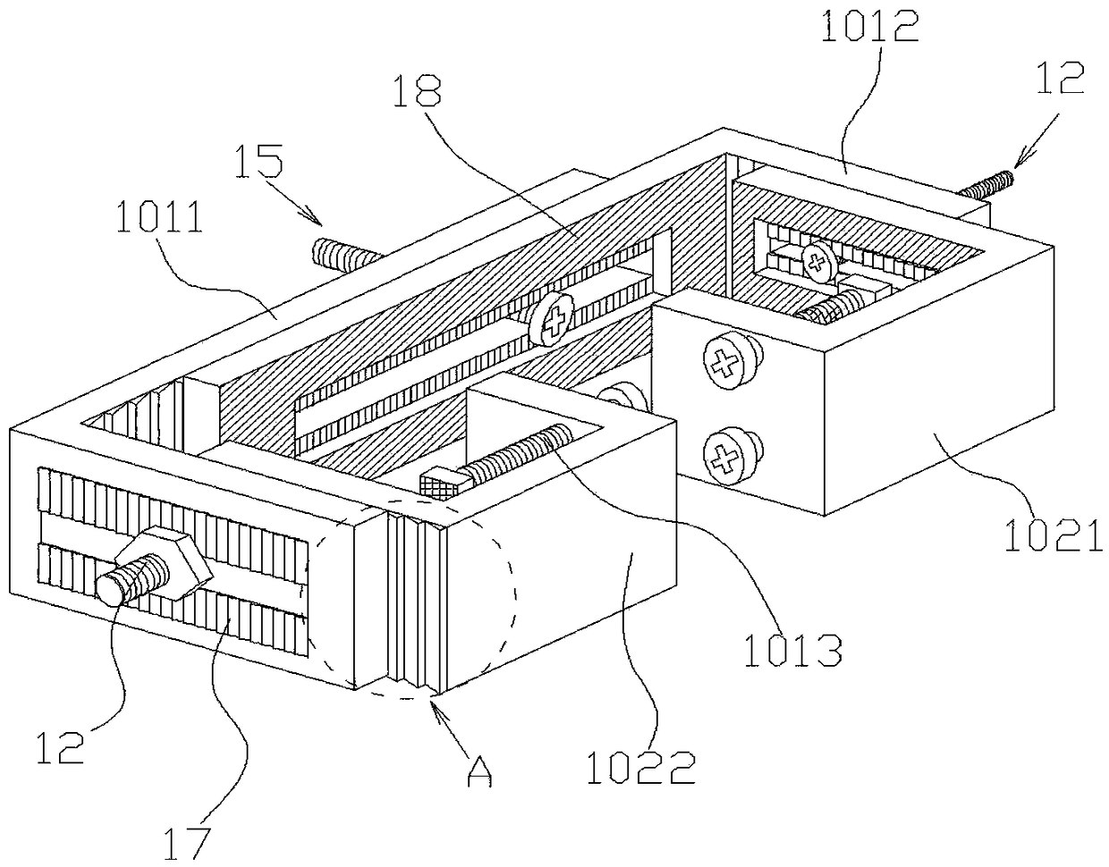
[0040] Figure 3 to Figure 6 A top-pressing elevator counterweight pressing piece provided by the second embodiment of the present invention is schematically shown.

[0041] like Figure 3 to Figure 6 As shown, a top-pressing elevator counterweight block pressing piece disclosed in the second embodiment of the present invention is basically the same as that in Example 1, and the difference lies in:

[0042] like Figure 3 to Figure 6 As shown, preferably, in order to prevent the loosening of the first bolt locking assembly 12 and the second bolt locking assembly 15 in the first adjustment groove 13 or the second adjustment groove 14, such as Figure 3 to Figure 5 As shown, in this embodiment of the present invention, the outer peripheral surfaces of one or both sides of the first adjusting groove 13 and the second adjusting groove 14 are provided with anti-skid lines 17, wherein the anti-skid lines 17 are elastic anti-skid layers attached or longitudinally arranged The anti...


PUM


Abstract

The invention provides a cover component of a top-pressing elevator weight block. The cover component of the top-pressing elevator weight block comprises a cover component body in a semi-rectangular shape as a whole. The cover component body is held on the outer of a U-shaped counterweight beam, and locked. The cover component body includes an outer locking block in the semi-rectangular shape and two inner locking blocks in the semi-rectangular shape which are correspondingly connected to the inside of both sides of the outer locking block. The two inner locking blocks are located on the U-shaped opening side of the counterweight beam and the outer locking block is located on the opposite side of the U-shaped opening side of the counterweight beam. The outer locking block and the inner locking blocks are locked through a first bolt locking assembly. The two inner locking blocks are correspondingly sandwiched outside of both side ends of the U-shaped opening side of the counterweight beam. Top pressing members are correspondingly arranged on the two inner locking blocks, and are pressed against inner walls of both sides of the counterweight beam. The top pressing members interact with the locking force of the outer side of the locking blocks to improve the locking performance.

Description

technical field [0001] The invention relates to the technical field of elevators, in particular to a top-pressure elevator counterweight pressing piece. Background technique [0002] The counterweight is an important part of the counterweight system. In order to ensure the smooth and comfortable operation of the elevator, the counterweight must be reliably fixed. In the prior art, a plurality of holes are opened on the vertical beam, the U-shaped compression structure is fixed on the heavy straight beam by long bolts, and the U-shaped compression structure is used to press the counterweight to realize the compression of the counterweight. The pressing scheme has the following problems: 1. The structure is complex and the production efficiency is low; 2. The straight beams are opened with a plurality of holes, and the processing procedures are numerous, and the efficiency is low; The performance and safety are reduced, and the wear degree of the CNC mold is also increased; 4...

Claims


Application Information

Patent Timeline
Patent Type & Authority Patents(China)
IPC IPC(8): B66B17/12B66B7/00
CPCB66B7/00B66B17/12
Inventor 朱爱民
Owner 朱爱民
Why Eureka
Try Eureka