Check patentability & draft patents in minutes with Patsnap Eureka AI!

Hydraulic clamping device

A hydraulic clamping and hydraulic technology, applied in the field of hydraulic clamping devices, can solve the problems of increasing the cost of goods, working for a long time, heavy physical exertion, etc., to achieve the effect of improving efficiency and reducing burden

Active Publication Date: 2017-07-14
KUNMING UNIV OF SCI & TECH
View PDF8 Cites 0 Cited by
  • Summary
  • Abstract
  • Description
  • Claims
  • Application Information

AI Technical Summary

Problems solved by technology

These two methods of fixing objects before lifting have their own limitations, such as the lift of a forklift, which makes the balance of the object during the lifting process completely dependent on the experience of the forklift driver, and there must be a certain gap at the bottom of the object. The fork can only enter to lift the object. The tethered hook type needs a long time of preparation before lifting the object, and has certain requirements for the object itself. If there is no hole that can be used for hooking, this will It makes it difficult and inconvenient to lift objects. Because of the inconvenience of fixing objects in the project, the handling of many heavy objects is still dominated by manpower. It is realized by manpower, which increases the cost of goods and poor work efficiency. The harsh working environment and heavy physical exertion have always hindered the efficient and rapid development of related industries.

Method used


Image

  • Hydraulic clamping device
  • Hydraulic clamping device
  • Hydraulic clamping device

Examples


Embodiment 1

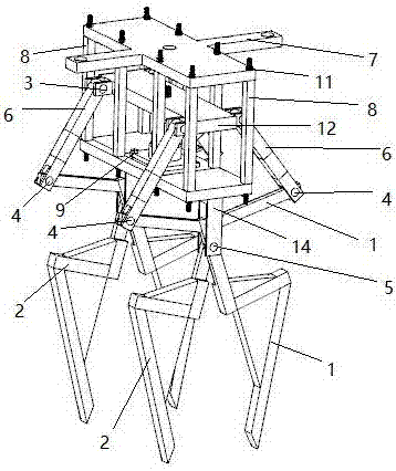
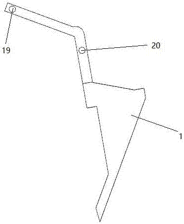
[0025] Embodiment 1: as Figure 1-12 As shown, a hydraulic clamping device includes clamping handle Ⅰ1, clamping handle Ⅱ2, round key Ⅰ3, round key Ⅱ4, round key Ⅲ5, connecting rod 6, upper base 7, bracket 8, bolt 9, nut Ⅰ10, nut Ⅱ11 , boom 12, hydraulic top 13, lower base 14, hole I15, hole II16, hole III17, hole IV18, hole V19 and hole VI20;

[0026] The thread at the upper end of the hydraulic jack 13 passes through the hole II16 in the middle of the boom 12, and the boom 12 is fixed on the hydraulic jack 13 by the threaded connection between the nut I10 and the thread at the upper end of the hydraulic jack 13, and the bolt 9 is passed through. Through the hole in the base of the hydraulic jack 13 and the hole III17 in the middle of the lower base 14, the hydraulic jack 13 is fixed on the lower base 14 with the threaded connection between the nut I10 and the bolt 9, and one end of the bracket 8 passes through the holes located around the lower base 14. Fix one end of the b...

Embodiment 2

[0029] Embodiment 2: as Figure 1-12 As shown, a hydraulic clamping device includes clamping handle Ⅰ1, clamping handle Ⅱ2, round key Ⅰ3, round key Ⅱ4, round key Ⅲ5, connecting rod 6, upper base 7, bracket 8, bolt 9, nut Ⅰ10, nut Ⅱ11 , boom 12, hydraulic top 13, lower base 14, hole I15, hole II16, hole III17, hole IV18, hole V19 and hole VI20;

[0030] The thread at the upper end of the hydraulic jack 13 passes through the hole II16 in the middle of the boom 12, and the boom 12 is fixed on the hydraulic jack 13 by the threaded connection between the nut I10 and the thread at the upper end of the hydraulic jack 13, and the bolt 9 is passed through. Through the hole in the base of the hydraulic jack 13 and the hole III17 in the middle of the lower base 14, the hydraulic jack 13 is fixed on the lower base 14 with the threaded connection between the nut I10 and the bolt 9, and one end of the bracket 8 passes through the holes located around the lower base 14. Fix one end of the b...

Embodiment 3

[0032] Embodiment 3: as Figure 1-12As shown, a hydraulic clamping device includes clamping handle Ⅰ1, clamping handle Ⅱ2, round key Ⅰ3, round key Ⅱ4, round key Ⅲ5, connecting rod 6, upper base 7, bracket 8, bolt 9, nut Ⅰ10, nut Ⅱ11 , boom 12, hydraulic top 13, lower base 14, hole I15, hole II16, hole III17, hole IV18, hole V19 and hole VI20;

[0033] The thread at the upper end of the hydraulic jack 13 passes through the hole II16 in the middle of the boom 12, and the boom 12 is fixed on the hydraulic jack 13 by the threaded connection between the nut I10 and the thread at the upper end of the hydraulic jack 13, and the bolt 9 is passed through. Through the hole in the base of the hydraulic jack 13 and the hole III17 in the middle of the lower base 14, the hydraulic jack 13 is fixed on the lower base 14 with the threaded connection between the nut I10 and the bolt 9, and one end of the bracket 8 passes through the holes located around the lower base 14. Fix one end of the br...


PUM


Abstract

The invention relates to a hydraulic clamping device, and belongs to the field of engineering machinery. A thread at the upper end of a hydraulic top penetrates through a second hole in the middle of a cargo boom, and the cargo boom is fixed to the hydraulic top through a thread between a first nut and the thread at the upper end of the hydraulic top in a connected mode; a bolt penetrates through a hole in a hydraulic top base and a third hole in the middle of a lower base, and the hydraulic top is fixed to the lower base through a thread between the first nut and the bolt in a connected mode; one end of a bracket is fixed to the lower base, and the other end of the bracket is fixed to an upper base; one end of each connection rod is connected with a fourth hole in the cargo boom through a first round key, and the other end of the connection rod is connected with a fifth hole in a first clamping handle or a second clamping handle through a second round key; and each first clamping handle and the corresponding second clamping handle are connected to a sixth hole in the lower base through sixth holes in the middle of the first clamping handle and the second clamping handle with a third round key. Through the hydraulic clamping device, the heavy cargo transport efficiency is improved, and the manual labor burden is relieved.

Description

technical field [0001] The invention relates to a hydraulic clamping device, which belongs to the field of engineering machinery. Background technique [0002] The lifting of heavy goods is a problem often encountered in engineering. Before lifting goods, the first step is to fix the object. The current method of fixing objects is mainly the lifting method of a forklift. The principle is to select two lifting points so that The object can achieve its own balance during the lifting process, or it can be fixed with a leash hook such as the common driving car in the factory. After the object is tied up with a rope, it can be hooked with the hook on the driving car or directly hooked with the hook on the driving car. Hold a hole in the object and lift the object. These two methods of fixing objects before lifting have their own limitations, such as the lift of a forklift, which makes the balance of the object during the lifting process completely dependent on the experience of ...

Claims


Application Information

Patent Timeline
Patent Type & Authority Applications(China)
IPC IPC(8): B66C1/44
CPCB66C1/447
Inventor 喻黎明唐兆家王凤花
Owner KUNMING UNIV OF SCI & TECH
Features
  • R&D
  • Intellectual Property
  • Life Sciences
  • Materials
  • Tech Scout
  • Unparalleled Data Quality
  • Higher Quality Content
  • 60% Fewer Hallucinations
Learn More