Exhaust gas purification device for internal combustion engine

A technology of exhaust gas purification device and internal combustion engine, which is applied to exhaust gas recirculation, charging system, mechanical equipment, etc., can solve the problems of increased weight and manufacturing cost, difficulty in packaging and layout, and difficulty in realizing compactness, and achieves weight reduction. , excellent packaging and layout, improve the effect of packaging and layout

Active Publication Date: 2017-07-14
HONDA MOTOR CO LTD
View PDF8 Cites 3 Cited by
  • Summary
  • Abstract
  • Description
  • Claims
  • Application Information

AI Technical Summary

Problems solved by technology

Therefore, it is necessary to form a double-layer pipe part with a high-temperature heat-resistant member such as a steel pipe or cast iron, which is more difficult to form than aluminum castings. Therefore, it is actually difficult to achieve compactness, and there are difficulties in packaging and layout.

Method used


Image

  • Exhaust gas purification device for internal combustion engine
  • Exhaust gas purification device for internal combustion engine
  • Exhaust gas purification device for internal combustion engine

Examples


Embodiment Construction

[0051] Hereinafter, one embodiment of the present invention will be described with reference to the drawings.

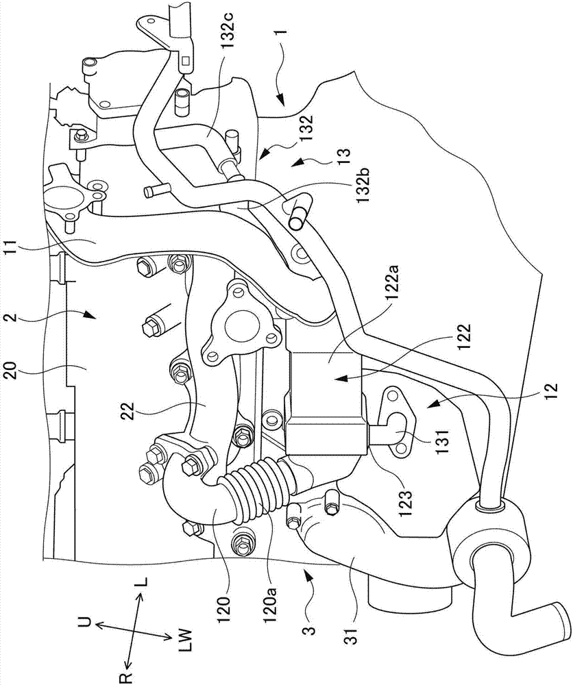
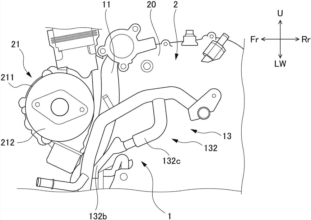
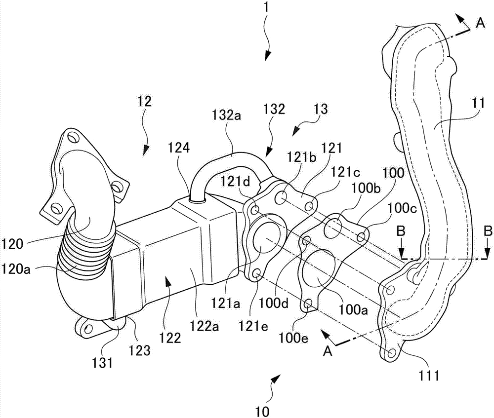
[0052] figure 1 It is a front view of an exhaust gas purification device 1 for an internal combustion engine according to an embodiment of the present invention. figure 2 It is a side view of the exhaust gas purification device 1 for an internal combustion engine according to the present embodiment. image 3 It is an exploded perspective view of the exhaust gas purification device 1 for an internal combustion engine according to the present embodiment. exist figure 1 and figure 2 Among them, U indicates upward, LW indicates downward, R indicates the right direction viewed from the driver, L indicates the left direction viewed from the driver, Fr indicates the front of the vehicle, and Rr indicates the rear of the vehicle.

[0053] Such as figure 1 and figure 2 As shown, the exhaust gas purification device 1 of the present embodiment is disposed on the vehicl...


PUM


Abstract

The present invention provides an exhaust gas purification device for an internal combustion engine, which has higher cooling efficiency than conventional ones, can be compacted with an inexpensive structure, and has excellent packaging and layout properties. The exhaust gas purification device (1) has: an EGR pipe (11), which returns the EGR gas to the intake passage; an EGR cooler (12), which is arranged on the EGR pipe, and a secondary internal combustion engine cooling circuit for cooling the engine (2). (3) The introduced cooling water performs heat exchange, thereby cooling the EGR gas; and the EGR cooling circuit (13), which connects the inlet (123) and outlet (124) of the cooling water formed on the EGR cooler with the internal combustion engine The cooling circuits are connected, and at least a part of the EGR cooling circuit passes through the connection portion (10) between the EGR pipe and the EGR cooler on the downstream side of the return flow direction of the EGR cooler, extends along the EGR pipe, and passes through a thermally conductive separating wall ( 110) It is integrally formed with the EGR pipe, and a sealing gasket (100) for sealing cooling water and EGR gas is arranged at the connecting portion.

Description

technical field [0001] The invention relates to an exhaust gas purification device of an internal combustion engine. More specifically, it relates to an exhaust gas purification device for an internal combustion engine including an EGR passage and an EGR cooler. Background technique [0002] Conventionally, there is known an exhaust gas purification device for an internal combustion engine including an EGR passage for returning a part of exhaust gas to the intake passage as EGR gas, and an EGR cooler for cooling the EGR gas. The EGR cooler is installed in the middle of the EGR passage, and cools the EGR gas by exchanging heat with cooling water introduced from an engine cooling circuit for cooling the internal combustion engine. [0003] In the above-mentioned EGR cooler, an inlet and an outlet for cooling water are formed, and an EGR cooling circuit that connects these inlets and outlets to the cooling circuit of the internal combustion engine is provided. This EGR coolin...

Claims


Application Information

Patent Timeline
IPC IPC(8): F02M26/28F02M26/32
Inventor 黑川纯一饭泉贵司上田谕三好一也
Owner HONDA MOTOR CO LTD
Why Eureka
Try Eureka