Air dividing structure, burner and fuel gas cooker

A burner and air intake technology, which is applied in the field of kitchen utensils, can solve the problems of unstable gas combustion and low gas flow rate, and achieve the effects of stable combustion and improved airflow speed and fluency

Active Publication Date: 2017-07-14
WUHU MIDEA SMART KITCHEN APPLIANCE MFG CO LTD
View PDF5 Cites 0 Cited by
  • Summary
  • Abstract
  • Description
  • Claims
  • Application Information

AI Technical Summary

Problems solved by technology

[0002] In the related technology, due to reasons such as the unreasonable design of the gas distribution

Method used


Image

  • Air dividing structure, burner and fuel gas cooker
  • Air dividing structure, burner and fuel gas cooker
  • Air dividing structure, burner and fuel gas cooker

Examples


Example Embodiment

[0026] The following describes the embodiments of the present invention in detail. Examples of the embodiments are shown in the accompanying drawings, wherein the same or similar reference numerals indicate the same or similar elements or elements with the same or similar functions. The following embodiments described with reference to the accompanying drawings are exemplary, and are only used to explain the present invention, but should not be understood as limiting the present invention.

[0027] In the description of the present invention, it should be understood that the terms "center", "longitudinal", "transverse", "length", "width", "thickness", "upper", "lower", "front", " "Back", "Left", "Right", "Vertical", "Horizontal", "Top", "Bottom", "Inner", "Outer", "Clockwise", "Counterclockwise" and other directions or The positional relationship is based on the position or positional relationship shown in the drawings, and is only for the convenience of describing the present in...


PUM


Abstract

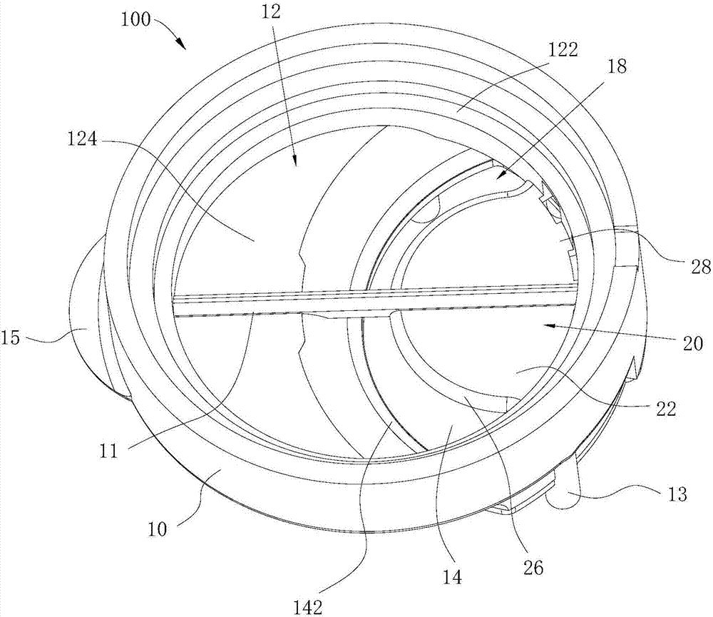
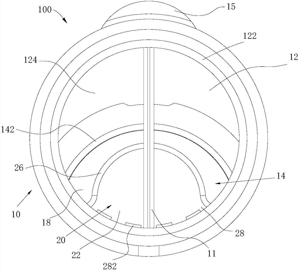
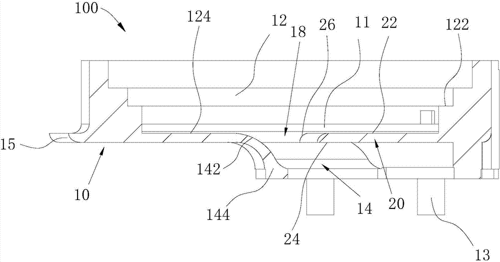
The invention discloses an air dividing structure, a burner and a fuel gas cooker. The air dividing structure comprises a body and a shielding piece. The body is provided with a chamber. An air inlet communicating with the chamber is formed in the bottom face of the chamber. The hole wall of the air inlet comprises the flow guiding face. The shielding piece is located in the air inlet. The shielding piece and the flow guiding face are oppositely arranged in a spaced mode and jointly form a flow guiding channel used for guiding an air flow into the chamber. According to the air dividing structure, air enters the chamber along the flow guiding channel, the air flow velocity and fluency of the air at the time of entering the chamber are greatly improved, and burning of fuel gas outside the air dividing structure is more stable.

Description

technical field [0001] The invention relates to the field of kitchen utensils, in particular to a gas distribution structure, a burner and a gas cooker. Background technique [0002] In the related art, due to reasons such as unreasonable design of the gas distribution structure of the burner, the flow rate of the gas gas is low, and the combustion of the gas is unstable. Contents of the invention [0003] The embodiment of the present invention provides a gas distribution structure for a burner. The gas distribution structure includes: [0004] A body, the body is provided with a chamber, the bottom surface of the chamber is provided with an air inlet communicating with the chamber, and the hole wall of the air inlet includes a guide surface; [0005] A baffle sheet located in the air inlet hole, the baffle sheet is spaced apart from the flow guide surface and together with the flow guide surface forms a flow guide channel for guiding gas into the chamber. [0006] In t...

Claims


Application Information

Patent Timeline
IPC IPC(8): F23D14/46F24C3/08
CPCF23D14/46F24C3/085
Inventor 赖育文余悦泳季俊生黄河
Owner WUHU MIDEA SMART KITCHEN APPLIANCE MFG CO LTD
Why Eureka
Try Eureka