
An arrayed resistance strain sensor and a measurement compensation system with the sensor

A technology of resistance strain and compensation system, which is applied in the direction of electric/magnetic solid deformation measurement, electromagnetic measurement device, and mitigation of undesired effects. Inapplicable and other problems, to achieve the effect of improving measurement accuracy, eliminating the influence of temperature drift, and preventing fracture

Active Publication Date: 2019-06-07
HUAZHONG UNIV OF SCI & TECH
View PDF11 Cites 0 Cited by
  • Summary
  • Abstract
  • Description
  • Claims
  • Application Information

AI Technical Summary

Problems solved by technology

For these problems, there are some solutions at present, such as a three-wire thermal resistance temperature measurement circuit scheme proposed in the patent CN101109662A, which can eliminate the influence of lead resistance when the temperature sensor is measured, but this method is only suitable for the measurement of a single temperature sensor. It is not suitable for the measurement of arrayed resistance strain sensor network, and the three-wire measurement scheme does not eliminate the influence of temperature error
Patent CN104470212A proposes a compensation method for circuit board impedance lines. Through impedance compensation, the interference of lead resistance can be reduced to a certain extent, but impedance compensation is only applicable to situations where there is no input and output. In intelligent skinning, structural health monitoring and many other fields are not applicable

Method used


Image

  • An arrayed resistance strain sensor and a measurement compensation system with the sensor
  • An arrayed resistance strain sensor and a measurement compensation system with the sensor
  • An arrayed resistance strain sensor and a measurement compensation system with the sensor

Examples


Embodiment Construction

[0031] In order to make the object, technical solution and advantages of the present invention clearer, the present invention will be further described in detail below in conjunction with the accompanying drawings and embodiments. It should be understood that the specific embodiments described here are only used to explain the present invention, not to limit the present invention. In addition, the technical features involved in the various embodiments of the present invention described below can be combined with each other as long as they do not constitute a conflict with each other.

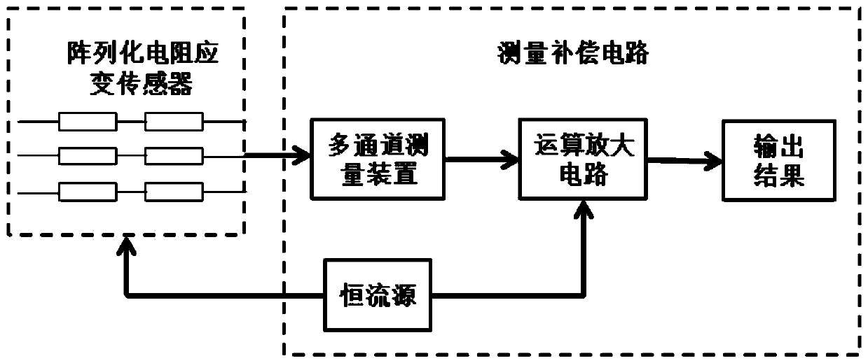
[0032] Such as figure 1 As shown, the present invention includes two parts, an arrayed resistance strain sensor and a measurement compensation circuit.

[0033] Such as figure 2 As shown, the arrayed resistance strain sensor in the present invention includes five parts: a flexible substrate 1 , a desensitization layer 2 , connecting leads 3 , a covering layer 6 and a resistance strain sensing...


PUM


Abstract

The invention belongs to the field of a strain measurement circuit, and discloses an array resistance strain sensor having a desensitization function. The array resistance strain sensor comprises a flexible substrate, desensitization layers, resistance strain sensing units, connecting leads and a cover layer. The resistance strain sensing units are attached to the upper surface of the flexible substrate and connected together through the connecting leads. The desensitization layers are arranged on the upper surface of the flexible substrate. The connecting leads are arranged on the upper surface of the desensitization layers. The cover layer is arranged on the flexible substrate and covers the desensitization layers, the resistance strain sensing units and the connecting leads. A layer of material having the desensitization function is arranged between the connecting leads and the flexible substrate so that the strain of the flexible substrate transmitted to the connecting leads can be reduced, the resistance strain affected on the connecting lines between different resistance strain sensing units is enabled to be quite low, the strain measurement accuracy can be effectively enhanced, and the connecting leads can also be protected and prevented from being broken to influence the working performance of the sensor.

Description

technical field [0001] The invention belongs to the field of strain measurement circuits, and more specifically relates to an arrayed resistance strain sensor and a measurement compensation system with the sensor. Background technique [0002] As a commonly used high-precision stress and strain measuring element, the resistance strain sensor is pasted on the surface of the measured object and deformed together with the measured object to measure the true strain of the component. [0003] With the development of electronic information technology and intelligent equipment, resistance strain sensors have been widely used in various fields, and correspondingly put forward higher requirements for strain sensor technology, especially in biomedical devices, which can be Wearable electronics, aircraft smart skin, and structural health monitoring require strain sensors to have performance indicators such as flexibility, large-area array measurement, and high precision. In order to m...

Claims


Application Information

Patent Timeline
Patent Type & Authority Patents(China)
IPC IPC(8): G01B7/16G01D3/028
CPCG01B7/18G01D3/028
Inventor 黄永安尹锋白云昭朱臣
Owner HUAZHONG UNIV OF SCI & TECH
Learn More