Combined high voltage DC circuit breaker with DC power flow control and control strategy thereof

A high-voltage DC, control-capable technology, applied to AC networks with different sources of the same frequency, emergency protection circuit devices, electrical components, etc. The composition cost of the DC power grid can be prevented, and the effects of preventing violent fluctuations, reducing repeated investment and reducing construction costs can be achieved.

Active Publication Date: 2017-07-14
ZHEJIANG UNIV
View PDF4 Cites 18 Cited by
  • Summary
  • Abstract
  • Description
  • Claims
  • Application Information

AI Technical Summary

Problems solved by technology

For this reason, several implementation forms of DC power flow controllers have been proposed in the literature, but this kind of power flow controller needs to add additional power electronic equipment, which increases the cost of the DC power grid.
[0006] In addition, both the DC circuit breaker and the DC power flow controller need to be connected in series in the DC line. At present, the external power supply is mainly used to supply the drive circuit of the IGBT in the device. Due to the high voltage level, it is difficult to achieve the insulation and withstand voltage indicators of the external power supply circuit. This defect greatly limits the application of DC power grid technology in the field of high voltage technology.

Method used


Image

  • Combined high voltage DC circuit breaker with DC power flow control and control strategy thereof
  • Combined high voltage DC circuit breaker with DC power flow control and control strategy thereof
  • Combined high voltage DC circuit breaker with DC power flow control and control strategy thereof

Examples


Embodiment Construction

[0030] In order to describe the present invention more specifically, the technical solutions of the present invention will be described in detail below in conjunction with the accompanying drawings and specific embodiments.

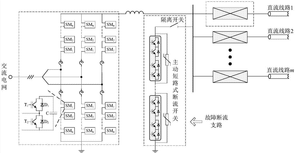
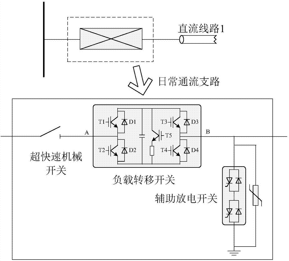
[0031] Such as figure 1 and figure 2 As shown, the combined high-voltage DC circuit breaker with DC power flow control capability of the present invention is composed of a fault interruption branch and a daily current flow branch, wherein the fault interruption branch includes an active short-circuit interruption switch and its isolating switch. The high-voltage end of the circuit is connected to the DC bus, and the low-voltage end is directly grounded. The number of its configuration is determined by the number of converter stations; the daily flow branch includes ultra-fast mechanical switches, load transfer switches, and auxiliary discharge switches. One end of the ultra-fast mechanical switches Connect the DC bus, the other end is connected to one e...


PUM


Abstract

The invention discloses a combined high voltage DC circuit breaker with DC power flow control and a control strategy thereof. The daily flow passage branch of the traditional combined high voltage DC circuit breaker is improved, a load transfer switch is changed from the original IGBT series into the full bridge sub-module series, and an overvoltage energy drain branch is additional provided. The invention controls the size of the positive resistance effect in the branch by controlling the frequency of the load transfer switch sub-module capacitor, so as to realize the purpose of the power flow control. Compared with the prior art, the load transfer switch of the circuit breaker topology of the invention has the dual function of the circuit breaker and the power flow controller, so as to reduce the repeated investment and reduce the construction cost of the power grid. In addition, the IGBT obtains power directly from the sub-module capacitor thereof while the external power supply is not required, the insulation problem difficult to solve in the project is avoided, and the application prospect in the high voltage DC power grid is enhanced.

Description

technical field [0001] The invention belongs to the technical field of power electronic systems, and in particular relates to a combined high-voltage direct current circuit breaker with direct current flow control capability and a control strategy thereof. Background technique [0002] The DC power grid is one of the important directions for the future development of my country's power grid. Compared with the traditional two-terminal DC transmission system, the DC power grid has the following advantages: (1) The economy of the system operation is greatly enhanced, and the traditional point-to-point transmission is changed to networked transmission. , reducing the number of converter stations required by the DC system, not only reducing the area occupied by the converter stations, saving transmission corridor resources, but also reducing the overall transmission loss of the system and reducing the difficulty of controlling the DC network; (2) The operating flexibility of the sy...

Claims


Application Information

Patent Timeline
Patent Type & Authority Applications(China)
IPC IPC(8): H02H7/26H02J3/06
CPCH02H7/268H02J3/06
Inventor 徐政刘高任肖晃庆肖亮
Owner ZHEJIANG UNIV
Why Eureka
Try Eureka