Three-phase rotating electrical machine

A rotating electrical machine, three-phase technology, applied in the field of three-phase rotating electrical machines, can solve the problem that the fractional slot structure cannot be used

Inactive Publication Date: 2017-07-14
AISIN SEIKI KK
View PDF9 Cites 4 Cited by
  • Summary
  • Abstract
  • Description
  • Claims
  • Application Information

AI Technical Summary

Problems solved by technology

Therefore, the technique of Patent Reference 4 cannot be used in fractional slot construction

Method used


Image

  • Three-phase rotating electrical machine
  • Three-phase rotating electrical machine
  • Three-phase rotating electrical machine

Examples


Embodiment Construction

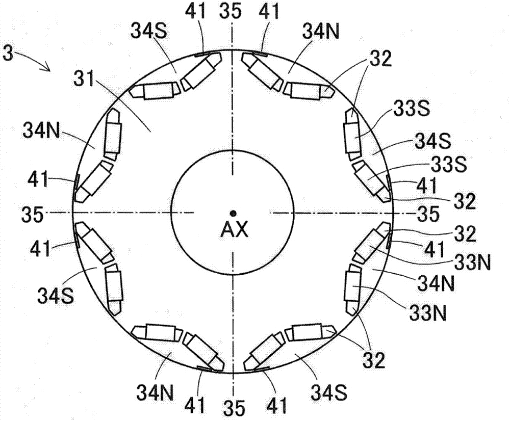
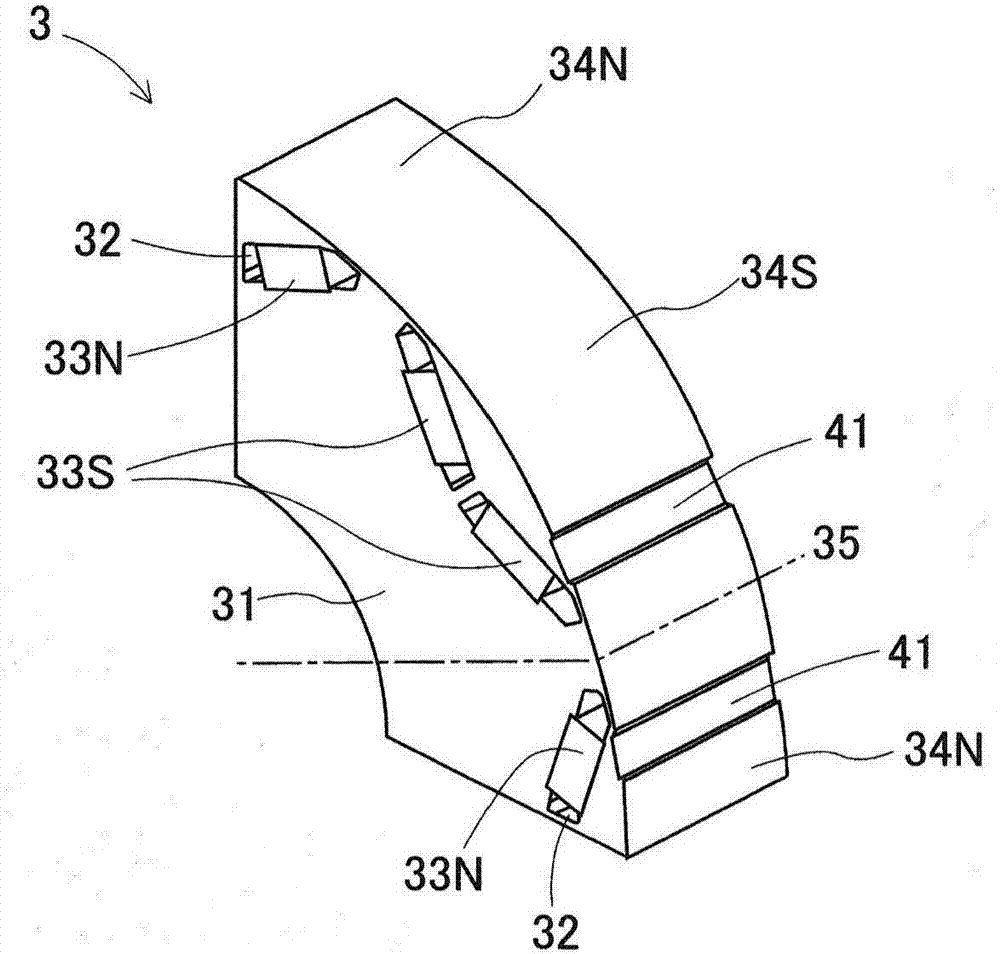
[0046] The first embodiment disclosed here and part of the second to eighth embodiments will be described. Embodiments disclosed herein relate to three-phase rotating electrical machines including a fractional slot configuration, wherein the number of slots per pole per phase is not an integer number, the number of slots per pole per phase is determined by dividing the number of slots of the stator by the poles of the movable element and further divided by 3 to obtain. will refer to figure 1 The general configuration of the three-phase rotating electrical machines 1 of the first to eighth embodiments of the present disclosure will be described. The three-phase rotating electrical machine 1 according to the first to eighth embodiments is mounted on, for example, a hybrid vehicle, and operates as a motor to drive the vehicle to run and as a generator to regenerate electric power at the time of braking. Therefore, three-phase rotating electrical machines operate over a wide ran...


PUM


Abstract

A three-phase rotating electrical machine includes a stator (2) including a stator core (21) provided with a plurality of teeth (23) and a plurality of slots (24), and winding (27), the three-phase rotating electrical machine including a rotor (3) including a rotor core (31) and a north magnetic pole (33N) and a south magnetic pole (33S), the three-phase rotating electrical machine including a fractional slot configuration, the rotor core including a north magnetic pole acting portion (34N), a south magnetic pole acting portion (34S), magnetic pole boundaries (35, 36, 361, 362) dividing the north magnetic pole acting portion and the south magnetic pole acting portion in the circumferential direction, and magnetic resistance portions (41, 42, 43, 441-444, 451-454, 461-464, 471-474), the magnetic resistance portion restricting the magnetic flux from passing through.

Description

technical field [0001] The present disclosure generally relates to a three-phase rotating electric machine. Background technique [0002] The purpose of the three-phase rotating electrical machine including the fractional slot configuration is to reduce torque ripple in the case where the three-phase rotating electrical machine is used as a motor, and to approximate the voltage wave to a sine wave in the case where the three-phase rotating electrical machine is used as a generator . However, in a three-phase rotating electrical machine including a fractional slot configuration, noise and / or vibration generated during operation may increase compared to a three-phase rotating electrical machine including an integer slot configuration. JP2003-32983A, JP2010-75049A, JP2002-165428A, and JP2000-69695A (hereinafter respectively referred to as Patent References 1 to 4) disclose reduction of noise and / or generated during operation of a three-phase rotating electric machine including...

Claims


Application Information

Patent Timeline
Patent Type & Authority Applications(China)
IPC IPC(8): H02K1/16H02K1/27
CPCH02K1/2766H02K3/12H02K21/14H02K29/03H02K2201/06H02K2213/03H02K1/165H02K1/276
Inventor 津田哲平佐久间昌史
Owner AISIN SEIKI KK
Why Eureka
Try Eureka