Al technical title is built by PatSnap Al team. It summarizes the technical point description of the patent document.
A dual-function, plotter technology, applied in the field of teaching instruments, can solve the problems of the plotter being unable to be operated manually, taking up a lot of space, and being limited in scope of use, achieving scientific and reasonable specification and size setting, good operability, and saving production. cost effect
Active Publication Date: 2018-09-04
QINZHOU UNIV
View PDF11 Cites 0 Cited by
Summary
Abstract
Description
Claims
Application Information
AI Technical Summary
This helps you quickly interpret patents by identifying the three key elements:
Problems solved by technology
Method used
Benefits of technology
Problems solved by technology
The invention adopts rack and pinion transmission to move the working platform left and right, and realizes the drawing of the displacement curve of the cam follower and the outline shape of the cam outer wheel, which is perceptual, but still has the following defects: the frame is divided into upper and lower layers , large volume, occupying space, and inconvenient to carry as a teaching aid; the drive mechanism of the workbench and the cam disc drive group are all driven by motors, the plotter cannot be manually operated, and the demonstration effect is poor, and the plotter depends on the power supply to work. The scope of use is limited
Method used
Image
Click on the blue label to locate the original text in one second.
Reading with bidirectional positioning of images and text.
Examples
Embodiment Construction
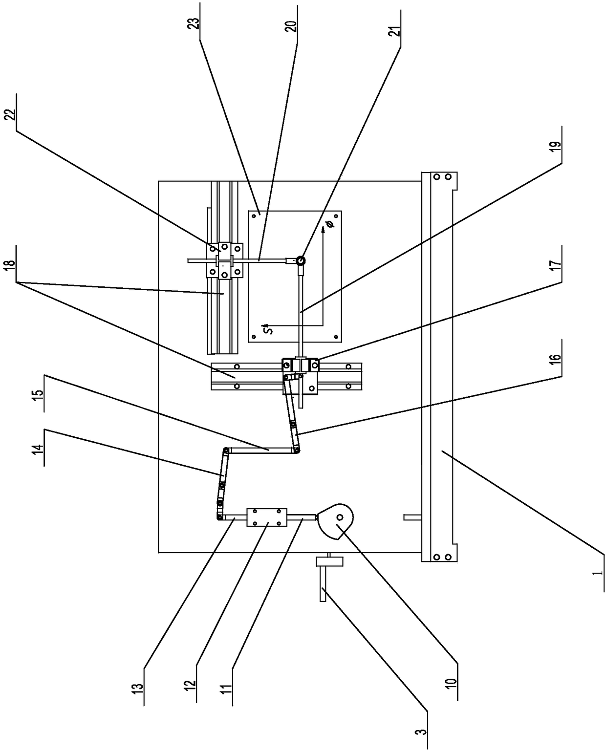
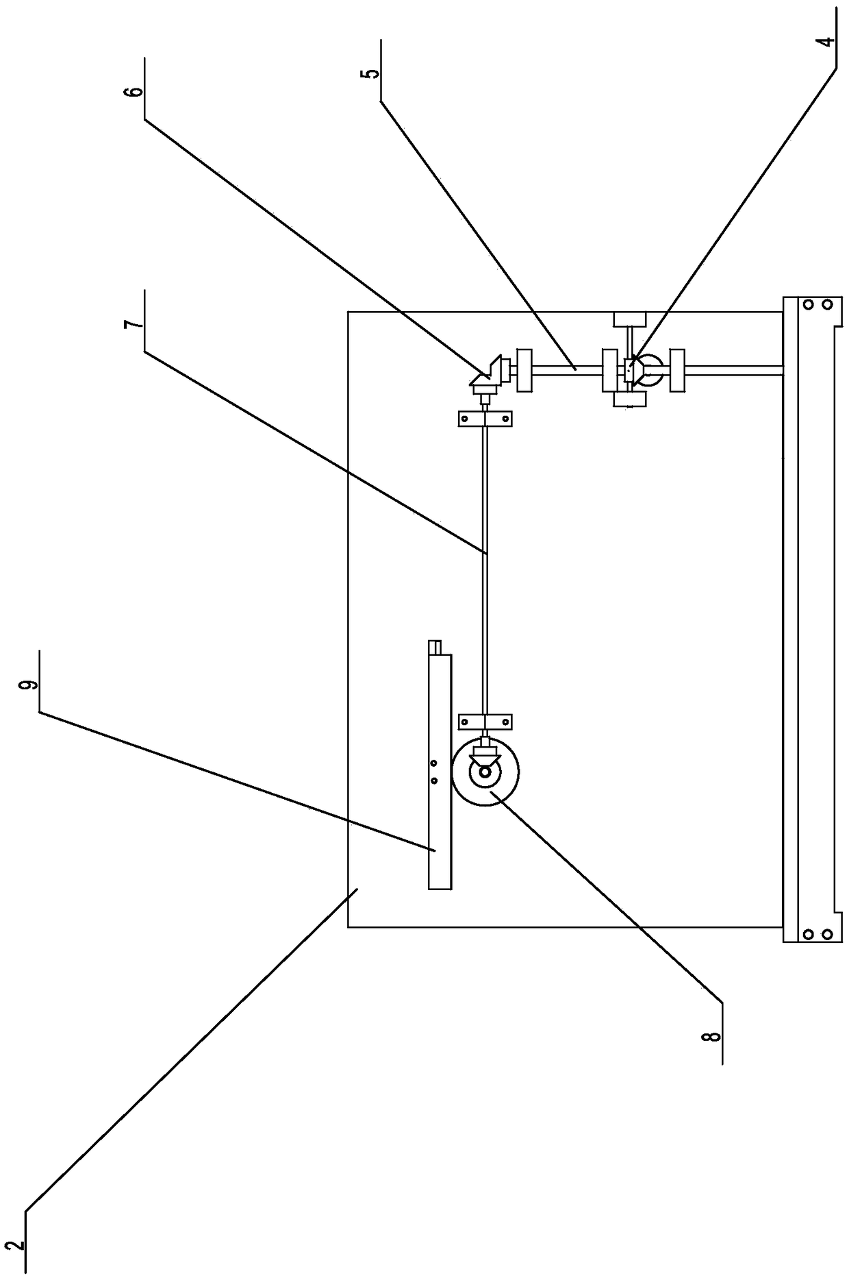
[0017] like figure 1 and figure 2 A specific embodiment of the present invention is proposed as shown, a dual-function cam track plotter, including a base 1, a rectangular support plate 2 disposed on the base 1, and a rotating handle 3 is provided at the side end of the support plate 2 , the rotary handle 3 is connected with the worm gear 4 on the back of the support plate, the worm gear 4 is provided with a vertical drive shaft 5, the end of the drive shaft 5 is connected with a pair of bevel gears 6 meshing with each other, the A connecting shaft 7 arranged horizontally is connected to the bevel gear 6, and a pair of bevel gears 6 meshing with each other are provided at the end of the connecting shaft 7, and a bevel gear 6 is meshed with a cylindrical gear 8, and the A horizontally arranged rack 9 is meshed on the cylindrical gear 8; the worm gear 4 is coaxially connected with the simulated cam 10 located on the front of the support plate 2, and there is a vertically arran...
PUM
Abstract
The invention provides a difunctional cam path plotting instrument which comprises a base and a support plate. A rotating handle is arranged at the side end of the support plate; the reverse side of the support plate is provided with a worm pair, a driving shaft, a bevel gear arranged at the end of the driving shaft, a connecting shaft, a bevel gear arranged at the end of the connecting shaft, a cylindrical gear and a rack; the obverse side of the support plate is provided with a simulating cam, a lower ejector rod, a screw-type quick replacing part, an upper ejector rod, a first connecting rod, a fixing rod, a second connecting rod, a vertical sliding block, linear sliding rails, a transverse paintbrush bar, a vertical paintbrush bar, a paintbrush and a transverse sliding block, and the transverse sliding block is connected with the rack. According to the plotting instrument, not only is plotting of a cam driven part displacement curve and an outer cam outline shape achieved, but also a fine adjusting function of the plotting instrument is achieved, the operability is good, and the demonstration property is high. In addition, the plotting instrument is compact in structure, small in size, low in mass, convenient to carry, suitable for any occasions and worthy of wide popularization.
Description
technical field [0001] The invention relates to a teaching instrument, in particular to a dual-function cam track plotter. Background technique [0002] The cam mechanism is generally a high-level mechanism composed of three components: the cam, the follower and the frame; the cam usually rotates continuously at a constant speed, and the follower is designed according to the application requirements to obtain a certain regular movement. The cam mechanism can realize complex motion requirements and is widely used in various automatic and semi-automatic mechanical devices. In the teaching of mechanical principles, the cam mechanism has always been the focus and difficulty in teaching. This part of knowledge is relatively abstract and difficult to understand. It is difficult for teachers to explain, and it is very difficult for students to understand. The existing cam track line measurement at home and abroad mainly includes the following two types: 1. In the existing teaching...
Claims
Application Information
Patent Timeline
Application Date:The date an application was filed.
Publication Date:The date a patent or application was officially published.
First Publication Date:The earliest publication date of a patent with the same application number.
Issue Date:Publication date of the patent grant document.
PCT Entry Date:The Entry date of PCT National Phase.
Estimated Expiry Date:The statutory expiry date of a patent right according to the Patent Law, and it is the longest term of protection that the patent right can achieve without the termination of the patent right due to other reasons(Term extension factor has been taken into account ).
Invalid Date:Actual expiry date is based on effective date or publication date of legal transaction data of invalid patent.