
Paperboard collecting machine

A technology of cardboard and crossbar, which is applied in the direction of stacking receiving device, sending objects, thin material processing, etc. It can solve the problems of over-tight conveyor belt, high maintenance and maintenance costs, and different lengths.

Active Publication Date: 2017-07-18
苏州庆丰包装材料有限公司
View PDF9 Cites 4 Cited by
  • Summary
  • Abstract
  • Description
  • Claims
  • Application Information

AI Technical Summary

Problems solved by technology

[0005] 1) The conveyor belt is too tight, and the cardboard is easy to slip
[0006] 2) If the conveyor belt is too loose, the cardboard will move up and down with the beating of the conveyor belt. Therefore, during the transmission process of the conveyor belt, it is very unstable, resulting in different lengths of the overlapping parts of two adjacent cardboards, and then As a result, the position of the cardboard delivered from the conveying device is different, which is also not conducive to the subsequent neat stacking work.
[0007] 3) The setting of the whole conveyor belt, maintenance and maintenance costs are relatively high
[0010] However, there are obvious substantive defects in the above-mentioned pressing device: since the pressure provided by the bead is constant and the position is also fixed, once the speed of the conveyor belt is too fast or the thickness and size of the cardboard change, it cannot Reasonable adjustments are required, resulting in singleness in use
[0012] However, in actual operation, because the speed of the cardboard output by the cardboard conveying device is difficult to balance, resulting in uneven layers on the outer side (both sides along the moving direction of the cardboard), once stacked, the height is large, and its center of gravity is unstable. Easy to collapse, which makes it difficult to transfer the cardboard

Method used


Image

  • Paperboard collecting machine
  • Paperboard collecting machine
  • Paperboard collecting machine

Examples


Embodiment Construction

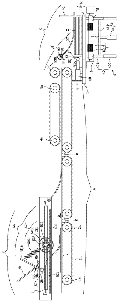
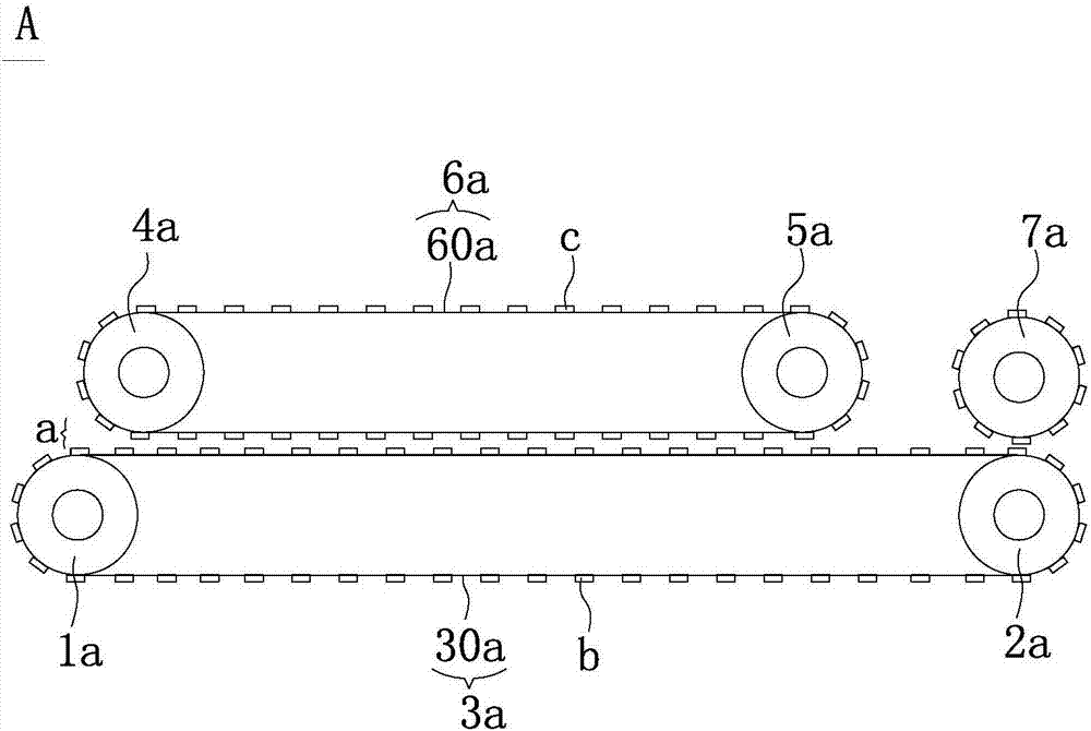
[0075] Such as Figure 1 to Figure 7 As shown, the cardboard collecting machine provided in this embodiment includes a collecting frame 1; a conveying device A, including a plurality of conveying units successively connected along the conveying direction of the cardboard; a counting device, which is used to count the number of cardboards after cutting; Pressing device B; stacking device C; central control system; at least one of the multiple conveying units can be set to be accelerated instantaneously. Continuously cut cardboard is set in batches in the transfer unit.

[0076] In this example, there are three transmission units (from left to right), and the three transmission units are connected by the receiving roller g rotating around its own axis. The transmission unit in the middle (the second transmission unit) can be set up instantly, and there are pressing devices on the first and second transmission units (in order to see the specific structure, the attached figure 1...


PUM


Abstract

The invention relates to a paperboard collecting machine. The paperboard collecting machine comprises first driving roller, second driving rollers and annular driving belts, wherein each first driving roller and each second driving roller horizontally extend in the direction perpendicular to the paperboard conveyance direction of the corresponding annular driving belt, each annular driving belt comprises multiple first annular partitioned belts arranged in the length direction of the corresponding first driving roller and the corresponding second driving roller at intervals. A conveying device further comprises a first compression roller, a second compression roller and an annular pressing belt, wherein the first compression roller and the second compression roller are arranged between the corresponding first driving roller and the corresponding second driving roller and located above the corresponding first driving roller and the corresponding second driving roller, and the corresponding first driving roller and the first compression roller rotate oppositely so that paperboards can move in the conveyance direction. The annular pressing belt comprises multiple second annular partitioned belts which are arranged in the length direction of the first compression roller and the second compression roller at intervals, wherein the first annular partitioned belts and the second annular partitioned belts are mutually parallel, a conveyance channel is formed, and the height of the conveyance channel can be adjusted. According to the paperboard collecting machine, the multiple vertically-corresponding annular partitioned belts clamp the top and bottom of the sequentially-stacked paperboards, so that the paperboards move relatively stable, cost is low, and the conveyance efficiency is high.

Description

technical field [0001] The invention relates to a cardboard collecting machine. Background technique [0002] The collection of cardboard is mainly to convey the cardboard output from the cross-cutting machine smoothly, and then stack it neatly to facilitate the subsequent packaging operation. Therefore, the cardboard collecting machine generally includes a conveying device, a pressing device, [0003] A stacking device for stacking cardboards, wherein the conveying device includes conveying rollers extending transversely and located at both ends, and a conveying belt sleeved on the conveying rollers. [0004] Although the above-mentioned conveying device can complete the conveying of the cardboard, once the conveying distance is too long, it has the following defects: [0005] 1) The conveyor belt is too tight, and the cardboard is easy to slip. [0006] 2) If the conveyor belt is too loose, the cardboard will move up and down with the beating of the conveyor belt. Theref...

Claims


Application Information

Patent Timeline
IPC IPC(8): B65H29/18B65H29/52B65H31/38B65H33/00
CPCB65H29/18B65H29/52B65H31/38B65H33/00B65H2404/256B65H2404/261
Inventor 许庆丰
Owner 苏州庆丰包装材料有限公司
Learn More