Power head guiding rail structure of drilling machine

A power head and guide rail technology, which is applied in earthwork drilling, drilling equipment, support devices, etc., can solve the problems of drill pipe and drilling rig centering mechanism wear, drilling rig power head guidance and orientation deterioration, low efficiency, etc., to achieve Maintain drilling accuracy, high coaxiality, and prevent shaking

Active Publication Date: 2017-07-18
ZHUHAI EAGLER SPECIALTY DRILLING EQUIP CO LTD
View PDF6 Cites 3 Cited by
  • Summary
  • Abstract
  • Description
  • Claims
  • Application Information

AI Technical Summary

Problems solved by technology

[0003] Since the square hole of the power head bracket is closed, the assembly of the power head bracket can only be pushed into the guide rail from both ends of the guide rail through special equipment and tools. The requirements for the assembly site and equipment are high, the assembly is difficult and the efficiency is low. It is difficult to replace the wear-resistant sheet later
[0004] The square hole of the power head bracket and the four mating surfaces of the guide rail are affected by the machining accuracy. There is a certain size error in the gap between the square hole and the guide rail surface. If the friction force of the power head bracket on the guide rail is to meet the design requirements, it must be The thickness of the wear-resistant sheet is matched according to different gaps, and the time period is long. This method is not conducive to mass production
[0005] Since the square hole of the power head bracket is closed, when the wear-resistant sheet is worn, the gap cannot be adjusted, causing the power head to shake during work, and the guiding and orientation of the drilling rig power head will become poor, which will eventually affect the drilling effect. Accelerates the wear of the drill pipe and the centralizing mechanism of the rig

Method used


Image

  • Power head guiding rail structure of drilling machine
  • Power head guiding rail structure of drilling machine
  • Power head guiding rail structure of drilling machine

Examples


Embodiment Construction

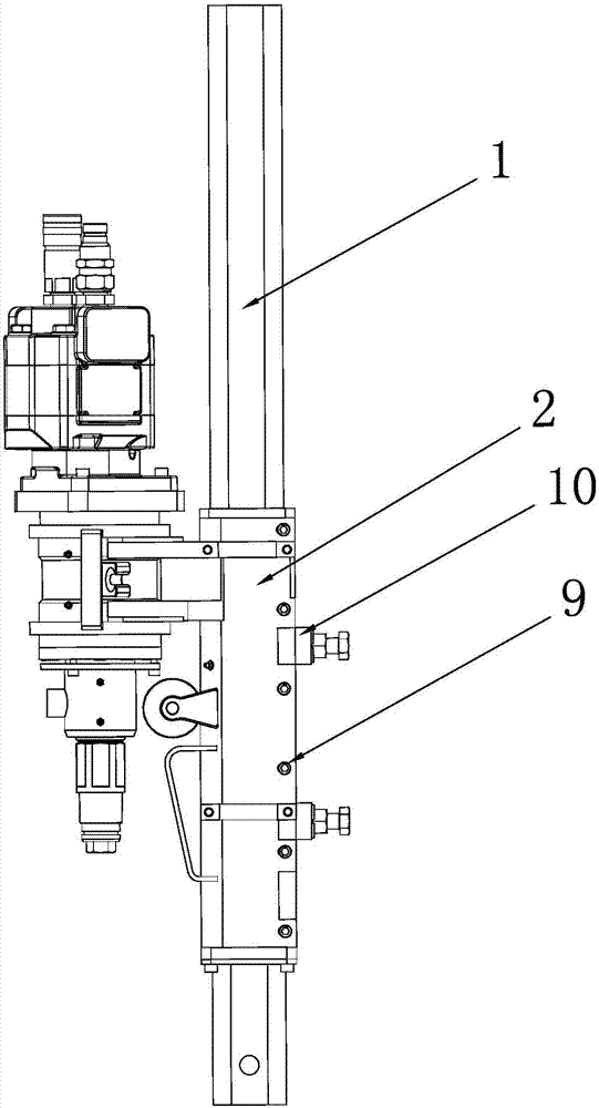
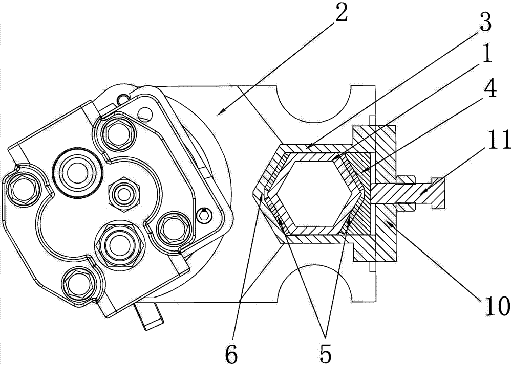
[0023] see figure 1 and figure 2 , a power head guide rail structure of a drilling rig according to the present invention, comprising a guide rail 1 installed on the drill bracket and a power head support 2 mounted on the guide rail 1 and movable along the guide rail 1, the power head support 2 is provided with upper and lower Through the guide groove 3 with opening on the right side, an adjustment block 4 is detachably installed on the right side of the guide groove 3 , and the position of the adjustment block 4 relative to the guide groove 3 is adjustable.

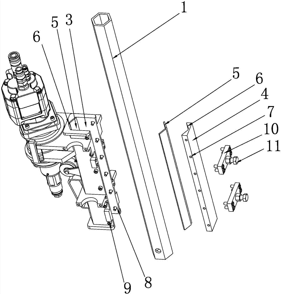
[0024] Specifically, as image 3 As shown, the front and rear sides of the adjustment block 4 are provided with threaded holes 7, and the front and rear side walls of the guide groove 3 are provided with strip holes 8, and the length direction of the strip holes 8 is in line with that of the guide rail 1. The axial direction is vertical, and the adjustment block 4 is installed in the guide groove 3 through the locking...


PUM


Abstract

The invention discloses a power head guiding rail structure of a drilling machine. The power head guiding rail structure comprises a guiding rail installed on a drilling machine support and a power head support installed on the guiding rail and capable of moving along the guiding rail. A vertically-through guiding groove with an opening in the right side is formed in the power head support, an adjusting block is detachably installed on the right side in the guiding groove, and the position, relative to the guiding groove, of the adjusting block can be adjusted. The adjusting block is matched with the guiding groove to clamp the guiding rail, and wear-resisting pieces are arranged between the left side of the guiding groove and the guiding rail as well as between the left side of the adjusting block and the guiding rail correspondingly. According to the power head guiding rail structure of the drilling machine, the guiding groove with the opening in one side is adopted for matching installation; the power head guiding rail structure is different from a traditional closed type guiding rail structure, components at the two ends of the guiding rail do not need to be specially detached and installed during assembly, assembly is easy, and the requirements for assembly places and equipment are reduced; and the wear-resisting pieces are convenient to adjust through the adjusting block, and friction force between the power head support and guiding rail can be adjusted after the wear-resisting pieces are worn, so that drilling accuracy of the drilling machine is kept for a long term, and a power head is prevented from wobbling.

Description

technical field [0001] The invention relates to the technical field of drilling rigs, in particular to a guide rail structure of a power head of a drilling rig. Background technique [0002] The guide rails of traditional drilling rigs are mostly quadrangular structures. The power head bracket is set on the guide rail through the square holes set on it. Wear-resistant sheets are set between the guide rail and the square holes of the power bracket. The power head bracket can slide up and down along the guide rail. [0003] Since the square hole of the power head bracket is closed, the assembly of the power head bracket can only be pushed into the guide rail from both ends of the guide rail through special equipment and tools. The requirements for the assembly site and equipment are high, the assembly is difficult and the efficiency is low. It is difficult to replace the wear-resistant sheet later. [0004] The square hole of the power head bracket and the four mating surface...

Claims


Application Information

Patent Timeline
Patent Type & Authority Applications(China)
IPC IPC(8): E21B15/00
CPCE21B15/003
Inventor 王坚
Owner ZHUHAI EAGLER SPECIALTY DRILLING EQUIP CO LTD
Why Eureka
Try Eureka