
Vertical air conditioner indoor unit

A technology for vertical air conditioners and indoor units, which is applied in air conditioning systems, heating methods, mechanical equipment, etc., can solve the problems of weakened fan output capacity, serious wind pressure loss, and reduced operating efficiency, and achieves simple structure, favorable heat exchange, The effect of reducing wind pressure loss

Active Publication Date: 2017-07-18
QINGDAO HAIER AIR CONDITIONER GENERAL CORP LTD +1
View PDF15 Cites 29 Cited by
  • Summary
  • Abstract
  • Description
  • Claims
  • Application Information

AI Technical Summary

Problems solved by technology

It can be seen that the distance of the airflow from the air inlet to the air outlet is longer, the wind pressure loss is more serious, the energy consumption is larger, the output capacity of the fan is weakened, and the operating efficiency of the whole machine is greatly reduced.

Method used


Image

  • Vertical air conditioner indoor unit
  • Vertical air conditioner indoor unit
  • Vertical air conditioner indoor unit

Examples


Embodiment Construction

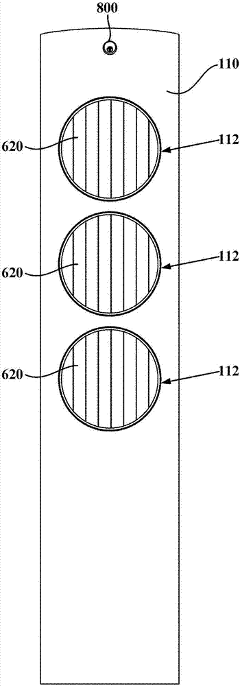
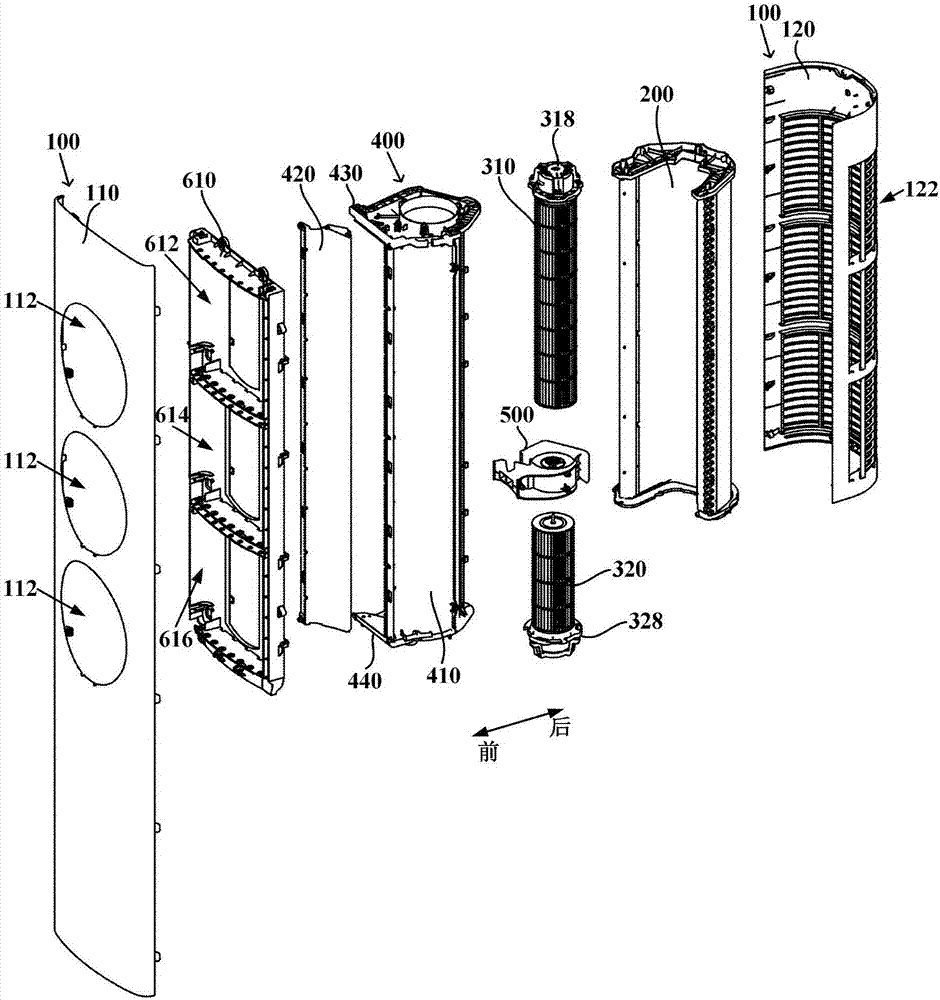
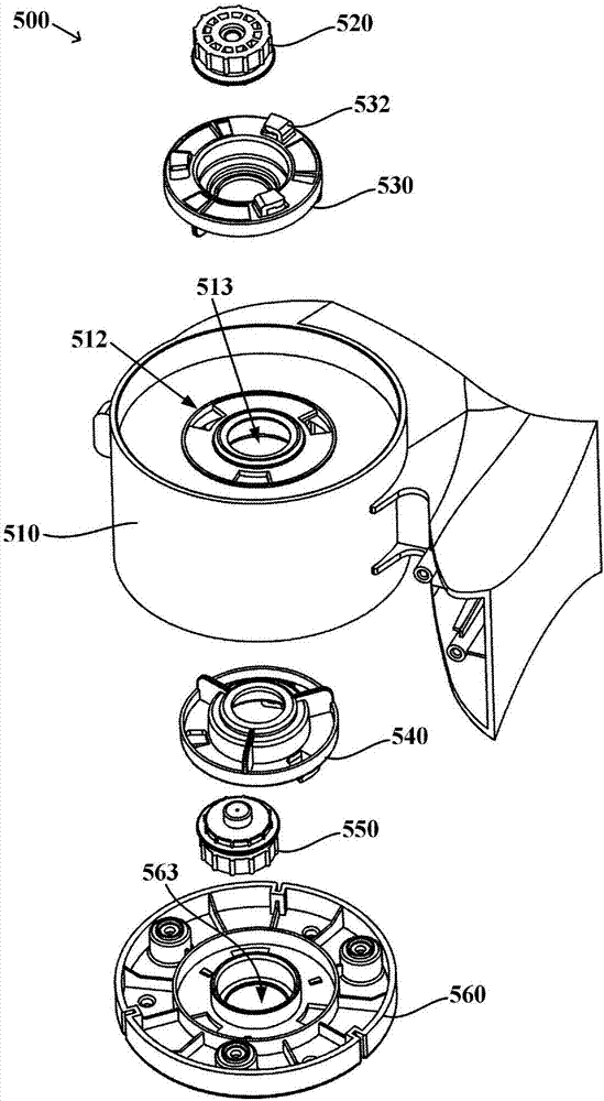
[0038] figure 1 is a schematic front view of a vertical air conditioner indoor unit according to an embodiment of the present invention; figure 2 yes figure 1 A schematic exploded view of the vertical air conditioner indoor unit shown. Such as figure 1 and figure 2 As shown, the vertical air conditioner indoor unit of the present invention may generally include a casing 100, a heat exchanger 200, two cross-flow fans, that is, a first cross-flow fan 310 and a second cross-flow fan 320, an air duct assembly 400 and Air duct divider 500 . Wherein, an accommodating space is defined inside the casing 100 for accommodating two cross-flow fans and the heat exchanger 200 . The casing 100 includes a front panel 110 on the front side, and a plurality of air outlets 112 arranged vertically are opened on the front panel 110 . An air inlet 122 is defined at a rear side of the casing 100 . Specifically, the rear side of the casing 100 may be an air inlet grill 120 , and an air inle...


PUM


Abstract

The invention provides a vertical air conditioner indoor unit. The indoor unit comprises a machine shell, a plurality of air outlets are vertically formed in a front panel, and the rear side of the machine shell is provided with an air inlet; a heat exchanger is arranged in the machine shell, a first cross flow fan and a second cross flow fan are vertically arranged in the machine shell, the axes vertically extend, the first cross flow fan and the second cross flow fan are collinear, and therefore the air is promoted to enter the machine shell via the air inlet and is subject to heat exchange with the heat exchanger to be blown out of the corresponding air outlet; an air flue assembly is erected on the circumferential outer sides of the first cross flow fan and the second cross flow fan so as to enable air to be led to the air outlets forwards from the heat exchanger, an air flue partition part is mounted on the air flue assembly and is located between the first cross flow fan and the second cross flow fan, space limited by the air flue assembly is partitioned into an upper portion and the lower portion, the first cross flow fan and the second cross flow fan are contained in the upper portion and the lower portion correspondingly, and the air flue partition part is provided with two bearings matched with a rotating shaft of the first cross flow fan and a rotating shaft of the second cross flow fan correspondingly. According to the indoor unit, the air flue assembly can be simplified, and the influence of the air flue assembly on the heat exchange efficiency of the heat exchanger can be reduced.

Description

technical field [0001] The invention relates to the technical field of air conditioning, in particular to a vertical air conditioner indoor unit. Background technique [0002] At present, traditional vertical air conditioner indoor units mostly use a centrifugal fan as a power source to drive air flow. The centrifugal fan and the heat exchanger are arranged in the casing of the indoor unit along the vertical direction, the air inlet is arranged at the lower part of the casing, and is opposite to the centrifugal fan, and the air outlet is arranged at the upper front side of the casing, and is connected with the heat exchange device. relatively. The air enters the casing through the air inlet at the lower part, flows through the air channel of the centrifugal fan and the heat exchanger in turn, and then is sent out from the air outlet at the upper part. It can be seen that the distance of the airflow from the air inlet to the air outlet is longer, the wind pressure loss is m...

Claims


Application Information

Patent Timeline
Patent Type & Authority Applications(China)
IPC IPC(8): F24F1/00F24F13/20F24F13/30F24F13/00F24F13/15F24F11/00
CPCF24F1/0025F24F1/0033F24F13/00F24F13/15F24F13/20F24F13/30F24F11/30F24F2120/10F24F2120/12F24F2120/14F24F1/005Y02B30/70
Inventor 杨怀波耿宝寒郝本华朱辉李国行
Owner QINGDAO HAIER AIR CONDITIONER GENERAL CORP LTD
Learn More