
Test device and test method for heart rate module

A test device and test method technology, applied in the field of communication, can solve the problems that the heart rate return value cannot be accurately judged whether it is within the accurate range, the LED flickering cannot accurately capture the optimal value of brightness, and the product affects the user experience, etc., to achieve test efficiency High, improve user experience, reduce the effect of light intensity signal interference

Active Publication Date: 2017-07-18
GEER TECH CO LTD
View PDF12 Cites 5 Cited by
  • Summary
  • Abstract
  • Description
  • Claims
  • Application Information

AI Technical Summary

Problems solved by technology

The existing heart rate detection method captures the optimal value of the brightness of the LED component by taking pictures of the CCD, but the LED flickering may not be able to accurately capture the optimal value of the brightness, and due to the interference and the influence of the shooting gap, the measurement can only be performed qualitatively, so It is impossible to determine whether the heart rate return value read at the moment is within the accurate range, and the accuracy of heart rate detection by the heart rate module is not only related to the algorithm, but also closely related to the module's assembly and material quality. Accumulation of errors can result in poorer performing products coming off the production line and entering the market
The detected heart rate results directly affect the user's judgment of physical health, so products with poor performance affect user experience and cause economic losses

Method used


Image

  • Test device and test method for heart rate module
  • Test device and test method for heart rate module

Examples


Embodiment Construction

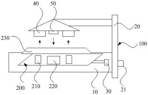
[0018] In order to make the purpose, technical solutions and advantages of the embodiments of the present invention clearer, the technical solutions in the embodiments of the present invention will be clearly and completely described below in conjunction with the drawings in the embodiments of the present invention. Obviously, the described embodiments It is a part of embodiments of the present invention, but not all embodiments. Based on the embodiments of the present invention, all other embodiments obtained by persons of ordinary skill in the art without creative efforts fall within the protection scope of the present invention.

[0019] The LED in the heart rate module is used to emit LED light intensity signals. If the performance of the heart rate module is abnormal, it will directly affect the data received by the heart rate receiver of the heart rate module; if the performance of the heart rate module is normal, the heart rate receiver should receive a stable value. B...


PUM


Abstract

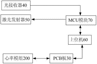
The invention relates to a test device and a test method for a heart rate module. The test device comprises a substrate used for carrying the heart rate module, a support structure arranged on the substrate, a PCB, an upper computer in communication connection with the heart rate module via the PCB, an MCU module in communication connection with the upper computer, an optical receiver used for receiving a light intensity signal emitted by an LED in the heart rate module, and a laser transmitter used for transmitting the light intensity signal to a heart rate receiving end of the heart rate module, wherein the optical receiver and the laser transmitter are corresponding to the heart rate module and arranged on the support structure; and both the optical receiver and the laser transmitter are in communication connection with the MCU module. The device and the method are used for measuring the light intensity signals transmitted and received by the LED in the heart rate module, and detecting whether the heart rate module is normal, so that reliability and accuracy of the heart rate module in use are improved, and user experience is enhanced.

Description

technical field [0001] The invention belongs to the technical field of communication, and in particular relates to a test device and a test method for a heart rate module. Background technique [0002] Whether the heart rate is normal is an important indicator to reflect the health of the human body. Always understand the changes in the heart rate of the human body, and maintain good health by adjusting living habits such as diet and exercise. The state of the human body is not static. The heart rate is different in different time periods and different physical states. Keep abreast of heart rate changes and prevent physical diseases in advance. [0003] At present, with the rise of smart wearable products, more and more sports bracelets and smart watches are on the market. Some of these smart wearable products are mainly aimed at monitoring physical health conditions, such as exercise conditions, heart rate, sleep conditions, etc. Therefore, Heart rate modules have been wid...

Claims


Application Information

Patent Timeline
IPC IPC(8): H04B10/079
CPCH04B10/0795
Inventor 柳勋
Owner GEER TECH CO LTD
Learn More