Compact type self-cleaning centrifuge

A self-cleaning and centrifuge technology, applied in the field of centrifuges, can solve the problems of affecting the centrifugal effect and bulky volume, and achieve the effects of simple and compact structure, improved centrifugal effect, and reduced height

Inactive Publication Date: 2017-07-21
ANHUI PUYUAN SEPARATION MACHINERY MFG CO LTD
View PDF9 Cites 9 Cited by
  • Summary
  • Abstract
  • Description
  • Claims
  • Application Information

AI Technical Summary

Problems solved by technology

There are still many unreasonable points in the existing centrifuge structure design, resulting in a relatively large volume, and in order to prevent the drum from being scratched, a safe distance is reserved between the scraper and the drum wall, which makes the scraper scrape every time When the material is finished, the filter cake with a certain thickness will always remain on the drum wall, which will affect its centrifugal effect.

Method used


Image

  • Compact type self-cleaning centrifuge
  • Compact type self-cleaning centrifuge
  • Compact type self-cleaning centrifuge

Examples


Embodiment Construction

[0039] Below, the technical solution of the present invention will be described in detail through specific examples.

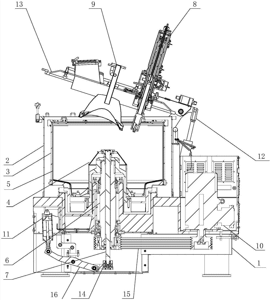
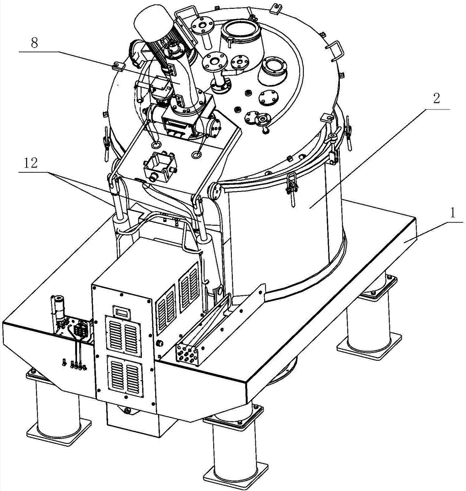
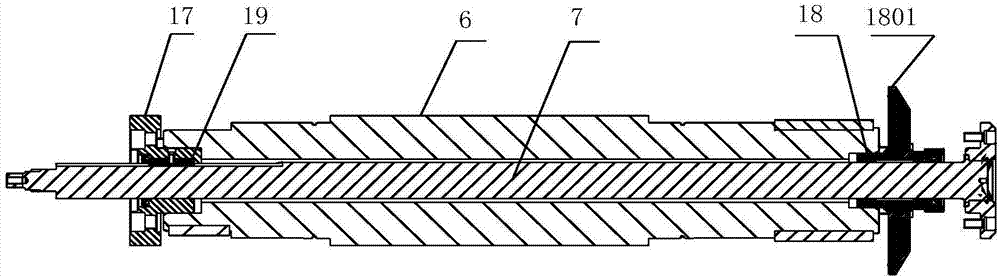
[0040] Such as Figure 1-5 as shown, figure 1 A structural schematic diagram of a compact self-cleaning centrifuge proposed by the present invention; figure 2 A schematic diagram of the appearance of a compact self-cleaning centrifuge proposed by the present invention; image 3 It is a schematic diagram of the assembly of the main shaft and the lifting shaft in a compact self-cleaning centrifuge proposed by the present invention; Figure 4 It is a structural schematic diagram of the rotary joint in a compact self-cleaning centrifuge proposed by the present invention; Figure 5 It is a structural schematic diagram of the filter bag in a compact self-cleaning centrifuge proposed by the present invention.

[0041] refer to Figure 1-2 , a compact self-cleaning centrifuge proposed by the embodiment of the present invention, including: a machine base 1, a cas...


PUM


Abstract

The invention discloses a compact type self-cleaning centrifuge which comprises a base, a shell, a drum, a lifting cover, a filtration bag, a main shaft, a lifting shaft, a scraping mechanism, a distribution mechanism, a first driving mechanism, a second driving mechanism and a third driving mechanism. The compact type self-cleaning centrifuge is simpler and more compact in structure through arrangement for the structure of the shell and parts in the corresponding positions in the shell, so that the overall height is greatly lowered. In addition, the lifting shaft and the main shaft are matched, the lifting cover can rotate synchronously with the drum and lift up and down relative to the drum at the same time, accordingly the filtration bag is pulled to retract up and down to remove materials stained on the wall of the drum and the filtration bag, and the purposes of self cleaning and improvement of the centrifugal effect of the centrifuge are achieved.

Description

technical field [0001] The invention relates to the technical field of centrifuges, in particular to a compact self-cleaning centrifuge. Background technique [0002] A centrifuge is a machine that uses centrifugal force to accelerate the separation of different materials that need to be separated. Centrifuges are widely used in chemical industry, petroleum, food, pharmaceutical, mineral processing, coal, water treatment and shipbuilding and other departments. There are still many unreasonable points in the existing centrifuge structure design, resulting in a relatively large volume, and in order to prevent the drum from being scratched, a safe distance is reserved between the scraper and the drum wall, which makes the scraper scrape every time When the material is finished, the filter cake with a certain thickness will always remain on the drum wall, which will affect its centrifugal effect. Contents of the invention [0003] Based on the technical problems in the above...

Claims


Application Information

Patent Timeline
Patent Type & Authority Applications(China)
IPC IPC(8): B04B7/08B04B15/06B04B7/16B04B7/02B04B11/08
CPCB04B7/08B04B7/02B04B7/16B04B11/08B04B15/06
Inventor 沈云翔张琼戚全利胡守志罗潇王世亮
Owner ANHUI PUYUAN SEPARATION MACHINERY MFG CO LTD
Why Eureka
Try Eureka