Double-motor coupling drive axle with torque directional distribution function

A technology of distribution function and coupling drive, which is applied to electric power units, power units, control units, etc., can solve the problem that the left and right output torque phases of the differential cannot be adjusted, and achieve high power requirements, compact structure, and improved cornering maneuverability. Effects of sex and driving pleasure

Active Publication Date: 2017-07-21
JILIN UNIV
View PDF5 Cites 18 Cited by
  • Summary
  • Abstract
  • Description
  • Claims
  • Application Information

AI Technical Summary

Problems solved by technology

[0007] The purpose of the present invention is to solve the defect that the left and right output torques of the differential are equal and cannot be adjusted in the traditional drive axle, and provide a dual-motor coupling drive axle with a torque-oriented distribution function

Method used


Image

  • Double-motor coupling drive axle with torque directional distribution function
  • Double-motor coupling drive axle with torque directional distribution function
  • Double-motor coupling drive axle with torque directional distribution function

Examples


Embodiment 1

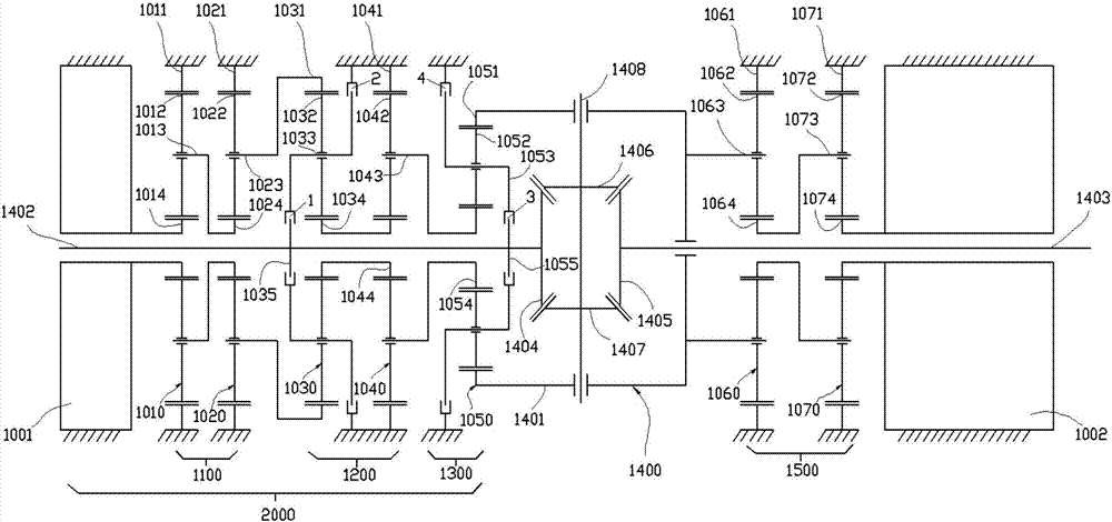
[0076] Such as figure 1 As shown, the dual-motor coupling transaxle with torque distribution function is mainly composed of a torque directional distributor 2000 , a traditional bevel gear differential 1400 , a main drive motor reduction mechanism 1500 and a main drive motor 1002 .

[0077] In this embodiment, the torque directional distributor 2000 is located on the left side of the drive axle, and it can also be exchanged with the main drive motor 1002, and it is arranged on the right side of the drive axle. The torque directional distributor 2000 is mainly controlled by the TV motor. 1001 , TV control motor reduction mechanism 1100 , double planetary row TV coupling mechanism 1200 , single planetary row differential coupling mechanism 1300 , first clutch 1 , second clutch 2 , third clutch 3 and fourth clutch 4 .

[0078] The TV control motor 1001 is a hollow shaft inner rotor motor, the first half shaft 1402 connected to the left wheel passes through the inner hole of the h...

Embodiment 2

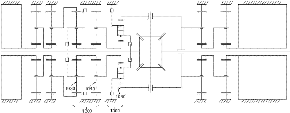
[0090] Such as figure 2 As shown, the first planetary gear train 1030 and the second planetary gear train 1040 in the double planetary row TV coupling mechanism 1200 are both single planetary gear planetary row, and the third planetary gear train 1050 in the single planetary row differential coupling mechanism 1300 It is a single-row double-stage planetary gear planetary row, and the structure diagram is shown in the figure. Other structures in this embodiment are completely the same as those in Embodiment 1.

Embodiment 3

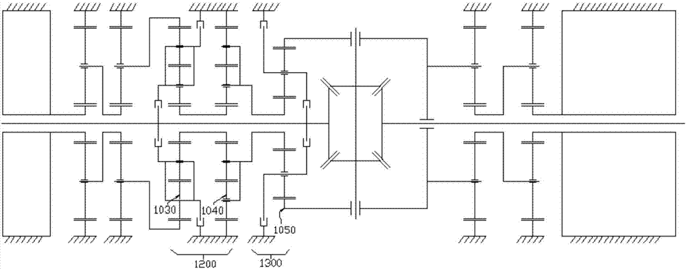
[0092] Such as image 3 As shown, the first planetary gear train 1030 and the second planetary gear train 1040 in the double planetary row TV coupling mechanism 1200 are both single-row double-stage planetary gear planetary row, and the third planetary gear train in the single planetary row differential coupling mechanism 1300 The gear train 1050 is a single planetary gear planetary row, and the structure diagram is as shown in the figure. Other structures in this embodiment are completely the same as those in Embodiment 1.


PUM


Abstract

The invention discloses a double-motor coupling drive axle with a torque directional distribution function. The double-motor coupling drive axle comprises a main driving mechanism, a bevel gear differential, a TV control driving mechanism, a first single-row planetary gear system, a second single-row planetary gear system, a third single-row planetary gear system, a first clutch, a third clutch, a second clutch and a fourth clutch. A first sun gear of the first single-row planetary gear system is rotatably supported on a first halt shaft, and a first gear ring is connected with the output end of the TV control driving mechanism. A second gear ring of the second single-row planetary gear system is fixed on a drive axle shell body, and a second sun gear is coaxially and fixedly connected with the first sun gear. A third sun gear of the third single-row planetary gear system is fixedly connected with a second planetary frame, and a third gear ring is fixedly connected with a differential shell. The first clutch is used for separating the first half shaft from a first planetary frame or connecting the first half shaft with the first planetary frame. The third clutch is used for separating the first half shaft from a third planetary frame or connecting the first half shaft with the third planetary frame. The second clutch is used for separating the first planetary frame from the drive axle shell body or connecting the first planetary frame with the drive axle shell body. The fourth clutch is used for separating the third planetary frame from the drive axle shell body or connecting the third planetary frame with the drive axle shell body.

Description

technical field [0001] The invention belongs to the technical field of electric vehicle drive, and in particular relates to a dual-motor coupling drive axle with torque orientation distribution function. Background technique [0002] Due to the increasingly serious problems of environmental pollution and energy crisis, more and more countries in the world have paid attention to the development of energy-saving and environment-friendly vehicles. Among them, electric vehicles, as a vehicle with almost zero emissions, have become the new darling of the automotive industry and have developed rapidly in recent years. Due to its inherent advantages, electric vehicles have great potential for development. [0003] At this stage, due to the poor heat dissipation of the motor and excessive unsprung mass of the electric vehicle driven by the hub motor, the technical bottlenecks cannot be solved. The electric vehicle generally adopts a powertrain composed of a single motor and a drive...

Claims


Application Information

Patent Timeline
Patent Type & Authority Applications(China)
IPC IPC(8): B60K1/02B60K17/04B60K17/16B60K17/02
CPCB60K1/02B60K17/02B60K17/04B60K17/16
Inventor 王军年杨斌
Owner JILIN UNIV
Why Eureka
Try Eureka