Hydraulic driving flexible robot joint

A robot joint and flexible technology, applied in the field of bionic robots, can solve problems such as heavy weight, disadvantageous robots, increase the complexity and nonlinearity of motor dynamics modeling, and achieve improved motion efficiency, reduced energy consumption, and reduced overall weight. Effect

Active Publication Date: 2017-07-21
HUAZHONG UNIV OF SCI & TECH
View PDF4 Cites 1 Cited by
  • Summary
  • Abstract
  • Description
  • Claims
  • Application Information

AI Technical Summary

Benefits of technology

This new technology allows for better control over robots that use hydrauled actuators due to its flexible connection between them and increased power-to-motion ratio during operation. It also improves the performance and lifespan of these robotic systems while reducing their size and mass.

Problems solved by technology

This patented describes how different parts on a robot can affect their behavior during movement or use by causing them to behave differently when they move around with varying speeds. These differences may lead to reduced overall functionality and weightiness issues that limit the ability of these components to function properly. Therefore, this technical solution involves developing new methods for controlling the movements of certain parts within the robot's body without adding extra weights or complicated mechanisms.

Method used


Image

  • Hydraulic driving flexible robot joint
  • Hydraulic driving flexible robot joint
  • Hydraulic driving flexible robot joint

Examples


Embodiment Construction

[0020] In order to make the object, technical solution and advantages of the present invention clearer, the present invention will be further described in detail below in conjunction with the accompanying drawings and embodiments. It should be understood that the specific embodiments described here are only used to explain the present invention, not to limit the present invention. In addition, the technical features involved in the various embodiments of the present invention described below can be combined with each other as long as they do not constitute a conflict with each other.

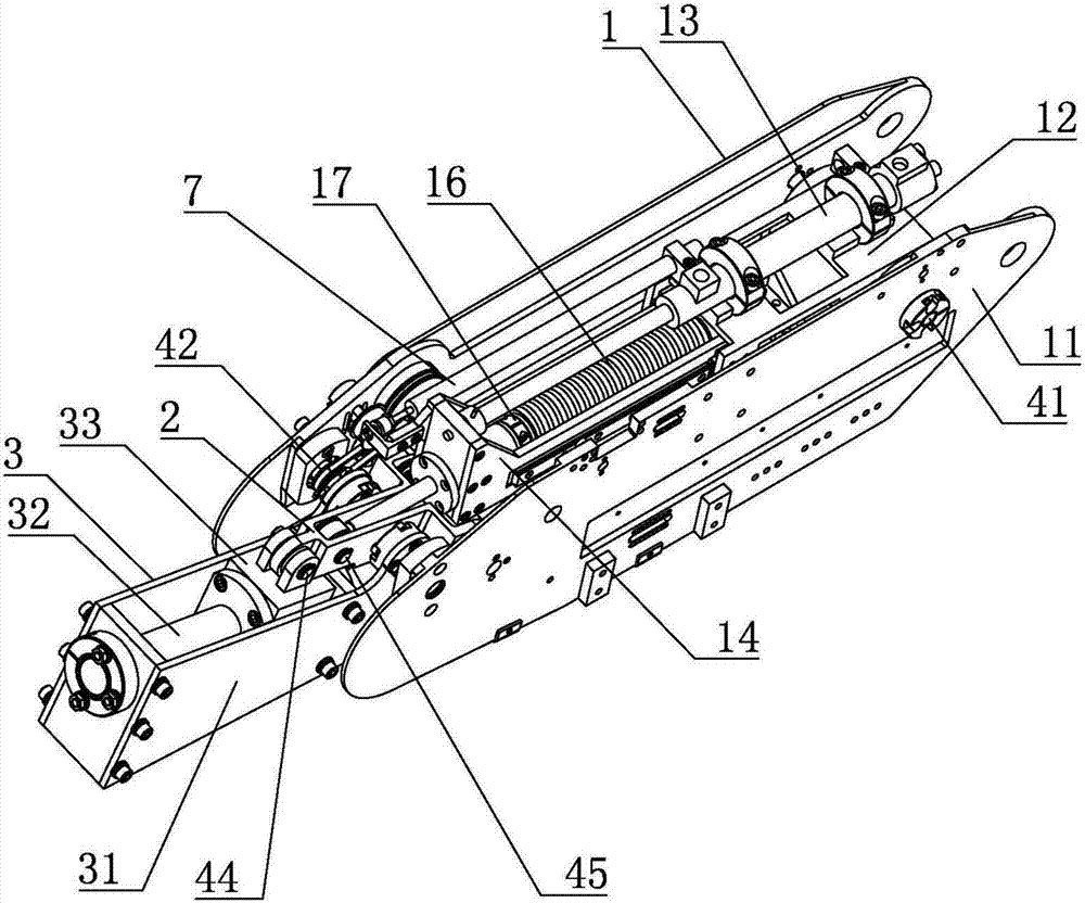
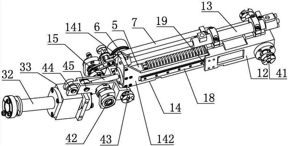
[0021] refer to Figure 1 ~ Figure 3 , a hydraulically driven flexible robot joint, including a thigh structure 1, a thigh structure 2 and a lower leg structure 3, wherein,

[0022] The thigh structure 1 includes a thigh main frame 11, a cylinder base 12, a hydraulic cylinder 13, a moving frame 14, a guide shaft 15 and a compression spring 16, and the cylinder base 12 is hinged to the thigh mai...


PUM


Abstract

The invention belongs to the field of bio-robots, and discloses a hydraulic driving flexible robot joint which comprises a thigh structure, a thigh-crus connecting frame and a crus structure. The thigh structure comprises a thigh body frame, a cylinder seat, a hydraulic cylinder, a movable frame, a guide shaft and a compression spring. The crus structure comprises a crus body frame, a guide rail and a slide block. The crus body frame is hinged to the thigh body frame. The guide rail is installed on the crus body frame. The slide block is installed on the guide rail. One end of the thigh-crus connecting frame is hinged to the thigh body frame, and the other end of the thigh-crus connecting frame is hinged to the slide block. In addition, the thigh-crus connecting frame is hinged to the end, away from the hydraulic cylinder, of the guide shaft. The hydraulic driving flexible robot joint can adapt to changes of external loads, have the bionic flexible characteristic and force arm characteristics, meet motion requirements of a robot, and can effectively reduce the total weight, achieve lightweight and improve the motion efficiency.

Description


Claims


Application Information

Patent Timeline
Owner HUAZHONG UNIV OF SCI & TECH
Why Eureka
Try Eureka