
A self-adaptive speed bump for signal-controlled intersections

A technology of signal-controlled intersections and speed bumps, applied in traffic signals, roads, buildings, etc., can solve the problems of poor waterproof performance of speed bumps, and achieve the effects of reducing traffic accident losses, ensuring waterproof effects, and shortening time delays

Active Publication Date: 2019-03-15
QINGDAO TECHNOLOGICAL UNIVERSITY
View PDF5 Cites 0 Cited by
  • Summary
  • Abstract
  • Description
  • Claims
  • Application Information

AI Technical Summary

Problems solved by technology

[0003] The purpose of the present invention is to provide an adaptive speed bump, which solves the technical problem of poor waterproof performance of the existing self-adaptive speed bump

Method used


Image

  • A self-adaptive speed bump for signal-controlled intersections
  • A self-adaptive speed bump for signal-controlled intersections
  • A self-adaptive speed bump for signal-controlled intersections

Examples


Embodiment Construction

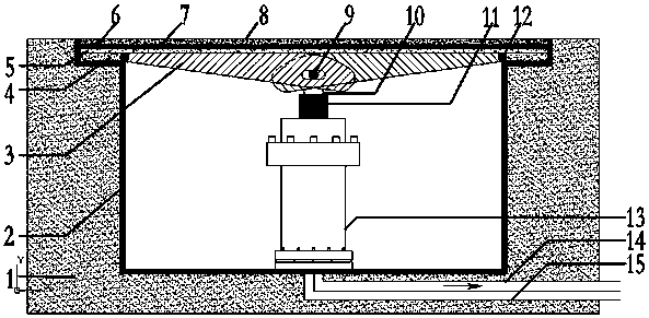
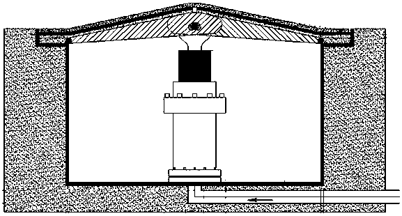
[0025] An adaptive speed bump for a signal-controlled intersection, comprising: a speed bump body module, a control module and an energy recovery module. The speed bump body module has a horizontal state and a raised state to provide the driver with accurate driving advice; the control module is used to control the speed bump body module to be in a horizontal state or a raised state according to the vehicle speed and the phase state of the intersection signal. When the module is in a raised state, the control module is used to control the speed bump body module to be in a soft state or an English state; the energy recovery module is used for the energy recovery part to use the flow of hydraulic oil to realize the conversion of the speed bump mechanical energy and electrical energy.

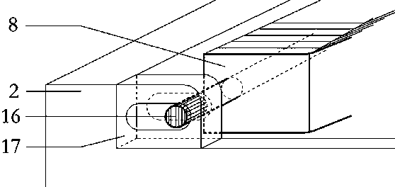
[0026] Such as Figure 1a , 1b As shown, the speed bump body module includes a speed bump box 2, a hydraulic cylinder 13, a connecting rod 9, an airfoil support plate 3 and a double-layer waterpro...


PUM


Abstract

The invention discloses a self-adaptive deceleration strip used for a signal-control intersection. The self-adaptive deceleration strip comprises a deceleration strip body module, a control module and an energy recovery module. The deceleration strip body module comprises wing type supporting plates, a hydraulic cylinder, a connecting rod, a double-layer waterproof structure and a protected box. The first wing type supporting plate and the second wing type supporting plate each comprise a tooth end and a hinging end hinged to the box, each hinging end is hinged to the deceleration strip box, and the tooth ends are engaged and provided with through holes. The connecting rod penetrates through the through holes, and a piston rod of the hydraulic cylinder is linked with the connecting rod, so that the first wing type supporting plate and the second wing type supporting plate are in a horizontal state or a protruding state to meet the requirements for the rise-fall states of the deceleration strip. Driving safety is judged in real time according to driving information of vehicles and signal phases of the intersection, and self-adaptive adjustment of three states including hard-state rising, soft-state rising and falling of the deceleration strip is conducted, so that a driver obtains correct decision information in time.

Description

technical field [0001] The invention belongs to the technical field of deceleration belts for traffic roads, in particular to an adaptive deceleration belt used for signal intersections. Background technique [0002] The intersection is the junction of the road network. When the signal lights at the intersection change, the driver can quickly judge whether to stop or pass according to the real-time road condition information. Because the driver's grasp of the intersection information is not completely accurate, it is very easy to make a wrong judgment, and even delay the passage. Time, heavy then cause traffic accident. In the 5 seconds before the red light at the intersection is turned on, there are problems such as traffic disorder, poor safety and low efficiency caused by the driver's unstable traffic behavior. In order to control the speed of the intersection at the intersection and assist the driver to make accurate decisions , there is an adaptive deceleration belt fo...

Claims


Application Information

Patent Timeline
Patent Type & Authority Patents(China)
IPC IPC(8): E01F9/529
Inventor 魏金丽杨金顺韩乐潍何继旭白坤郑甜甜
Owner QINGDAO TECHNOLOGICAL UNIVERSITY
Learn More