Wave making method for generating continuous focused waves in wave water tank within short time

A short-time, wave technology, applied in hydraulic models and other directions, can solve the problems of long-term, continuous focused wave simulation without public reports, exceeding the test sampling capacity, etc., to improve efficiency, shorten the sampling time, and meet the wave trough test. effect of demand

Active Publication Date: 2017-07-21
HARBIN INST OF TECH
View PDF5 Cites 12 Cited by
  • Summary
  • Abstract
  • Description
  • Claims
  • Application Information

AI Technical Summary

Problems solved by technology

Although the flume wave-making technology has been developed relatively well, there is no public report on continuous focused wave wave simulation. The previous focused-wave wave-making method can only generate a single focused wave. Long time, this time generally greatly exceeds the test sampling capacity

Method used


Image

  • Wave making method for generating continuous focused waves in wave water tank within short time
  • Wave making method for generating continuous focused waves in wave water tank within short time
  • Wave making method for generating continuous focused waves in wave water tank within short time

Examples


Embodiment 1

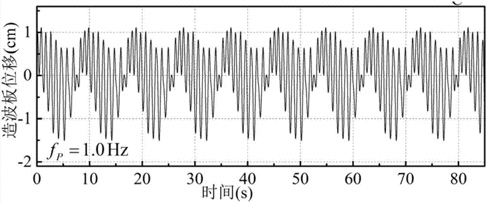
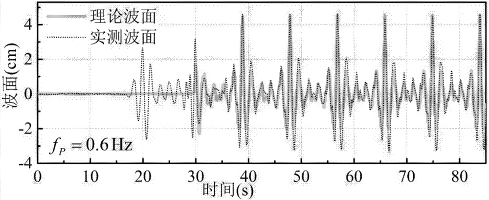
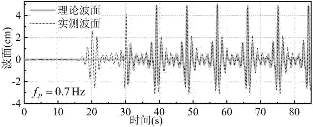
[0067] Such as Figure 1-8 As shown, the effectiveness and accuracy of the continuous focused wave wave-making method proposed by the present invention are verified through specific wave tank tests.

[0068] A wave-making method that generates continuous focused waves in a wave tank in a short period of time, using a push plate type wave-making machine to make waves. The specific method is as follows: Based on the principle of linear superposition, the two-dimensional wave surface can be expressed as:

[0069]

[0070] in:

[0071] N f - total number of component harmonics;

[0072] a i —Amplitude of constituent waves (m);

[0073] k i ——the number of constituent waves;

[0074] ω i ——Composition angular frequency (rad / s);

[0075] φ i —Initial phase of the constituent waves (rad).

[0076] Wavenumber and frequency satisfy the dispersion relation:

[0077] ω i 2 =gk i tanh(k i d) (2)

[0078] in:

[0079] g—gravitational acceleration (the value is 9.8m / s 2...

Embodiment 2

[0113] A wave-making method that produces continuous focused waves in a wave tank in a short period of time. It uses a rocker-type wave-making machine to generate waves. The specific method and theoretical derivation process are similar to those of the push-plate type, except that it is different in calculating the displacement signal of the rocker plate. The following will be explained in turn.

[0114] The wave surface function at the focal point of the continuous focused wave in the tank has nothing to do with the type of the wave maker. The wave surface of the continuous focused wave generated by the wave maker equipped with a rocking plate at the focal point is still Equation (13), and at the position of the wave maker The wave surface of is formula (14). Hydraulic transfer function T(f i )for:

[0115]

[0116] The wave surface time history curve of each frequency component included in it can be brought back to formula (11) to obtain the motion signal of the wave-ma...


PUM


Abstract

The invention provides a wave making method for generating continuous focused waves in a wave water tank within a short time. A push-plate-type or swing-plate-type wave maker is adopted to generate waves, and the wave making method generating the multiple focused waves can be deduced through the principle based on single focused waves. By the adoption of the method, push-plate-type wave maker displacement signals capable of being used for generating the continuous focused waves in the wave water tank can be obtained, the displacement signals are loaded into a wave maker wave making system, and accordingly the continuous focused waves can be generated in the water tank. Through specific wave water tank experiments, effectiveness and accuracy of the continuous focused wave making method provided by the invention are verified. By means of the wave making method provided by the invention, the multiple focused waves can be generated in the wave water tank within a short time, repeated trials of the focused waves are turned into a feasible scheme, sampling time used in the testing process can be greatly shortened, and the water tank testing efficiency is improved.

Description

technical field [0001] The invention relates to offshore and marine engineering hydrodynamic wave tank test technology, in particular to a wave-making method for generating continuous focused waves in a wave tank within a short period of time. Background technique [0002] In recent decades, human beings have been exploring the ocean more and more, and the demand for ocean energy, marine transportation and other fields has also increased. The exploitation of marine energy and the implementation of marine transportation are inseparable from the infrastructure of marine and offshore engineering. The safety of these engineering structures has become a key factor in ensuring human marine activities. Under complex marine environmental conditions, offshore or marine structures cannot avoid the extreme disasters at sea, such as tsunami, huge waves caused by hurricanes, and large waves in sea conditions, like ships, so its design must take into account the sea. In the worst case s...

Claims


Application Information

Patent Timeline
Patent Type & Authority Applications(China)
IPC IPC(8): E02B1/02
CPCE02B1/02
Inventor 方庆贺郭安薪李惠
Owner HARBIN INST OF TECH
Why Eureka
Try Eureka