Fixing and adjusting device for engine pipeline

An engine and pipeline technology, applied in the field of engine pipeline fixed and adjustable devices, can solve problems such as damage and increase the probability of pipeline damage, and achieve the effects of improving assembly efficiency, reducing the probability of pipeline scrapping, and facilitating maintenance and loading and unloading

Active Publication Date: 2017-07-21
AECC SHENYANG ENGINE RES INST
View PDF7 Cites 4 Cited by
  • Summary
  • Abstract
  • Description
  • Claims
  • Application Information

AI Technical Summary

Problems solved by technology

[0003] During the pipeline installation process, due to the fixed position of the bracket for fixing the pipeline, it is often necessary to correct the shape of the pipeline caused by welding, heat treatment and other factors to meet the requirements of stress-free assembly. Damage caused by welding parts of joints or other weak parts objectively increases the probability of damage to pipelines

Method used


Image

  • Fixing and adjusting device for engine pipeline
  • Fixing and adjusting device for engine pipeline
  • Fixing and adjusting device for engine pipeline

Examples


Embodiment 1

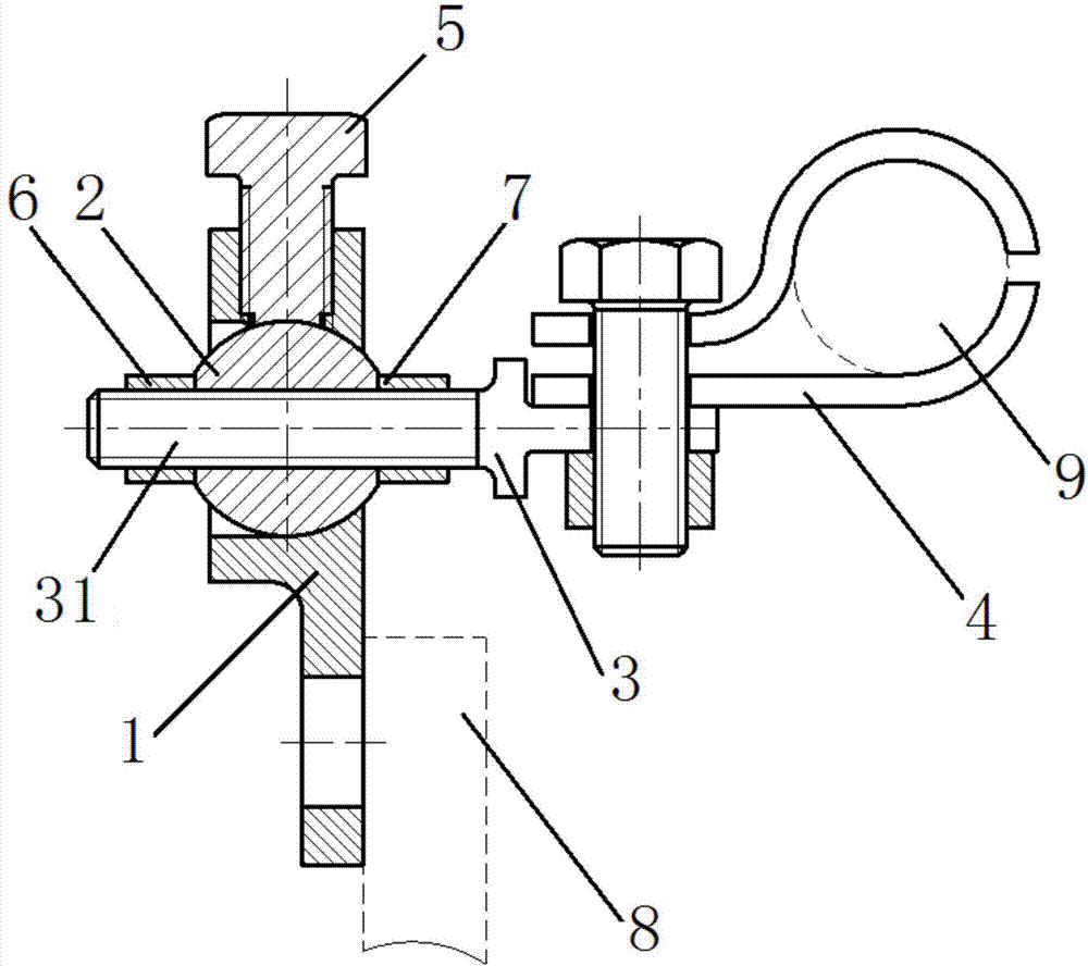
[0027] Such as figure 1 As shown, the present invention provides an engine pipeline fixing and adjustable device, including a bracket 1, a ball 2, a pole 3, a clip 4 and an adjustment and fixing assembly. In this embodiment, the adjustment and fixing assembly is a jacking screw 5 ;

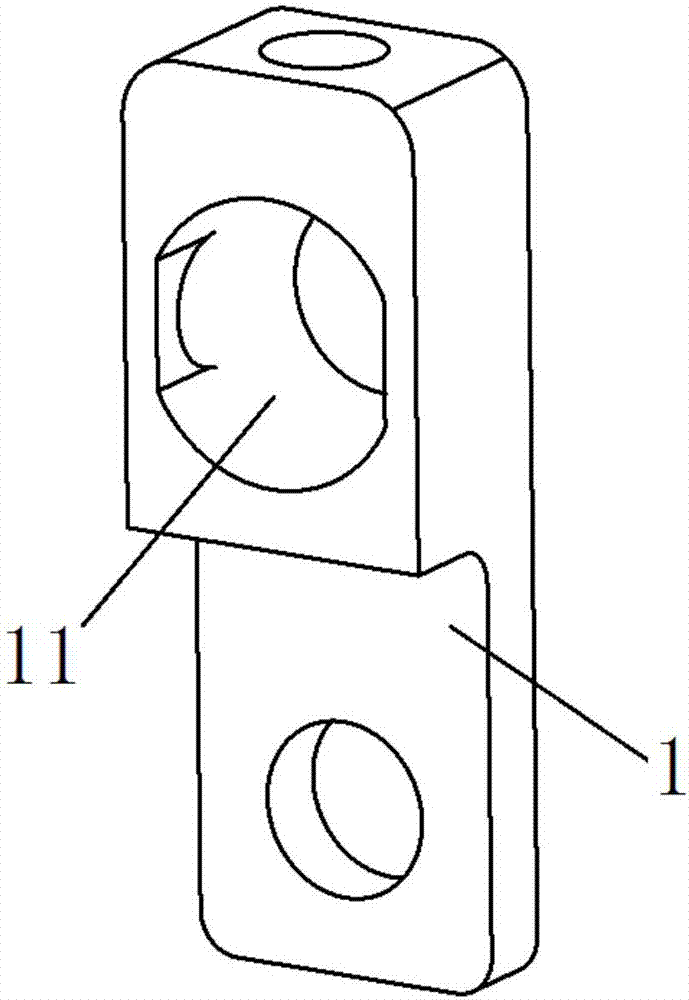
[0028] The three-dimensional schematic diagram of support 1 in this embodiment is as follows figure 2 As shown, the bracket 1 is provided with a spherical hole 11 that runs through the bracket 1, and a threaded hole for installing the jacking screw 5 is provided on the bracket 1. The threaded hole of the bracket 1 communicates with the spherical hole 11 and is located in the spherical hole. 11 directly above, the bracket 1 and the casing 8 are fixed, preferably, the casing 8 and the bracket 1 are fixed by bolts;

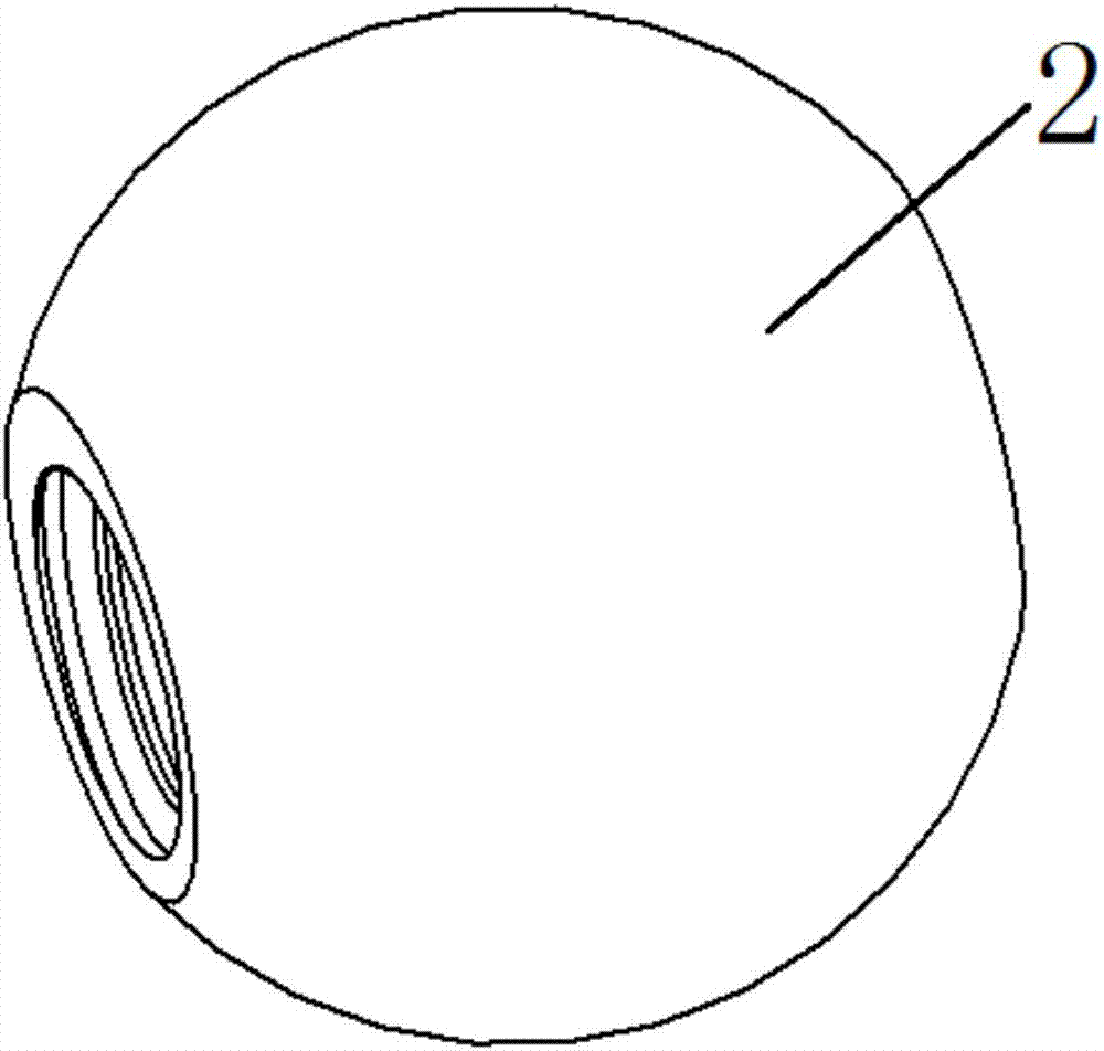
[0029] The three-dimensional schematic diagram of sphere 2 is shown in image 3 As shown, the sphere 2 is spherical and installed in the spherical hole 11, the spherical surface of t...

Embodiment 2

[0033] The three-dimensional schematic diagram of support 1 in this embodiment is as follows Figure 5 As shown, the bracket 1 is provided with two threaded holes for installing jacking screws 5, the threaded holes of the two brackets 1 are connected with the spherical hole 11, and the axes of the two jacking screws 5 pass through the sphere 2, the screw ends of the two jacking screws 5 are made of elastic rubber material, and the end faces of the screw ends are all concave spherical surfaces, and the concave spherical surface is in contact with the spherical surface of the sphere 2, that is, the sphericity of the concave spherical surface and the spherical surface of the sphere 2 The spherical degree of the contact part with the concave spherical surface is the same, and the sphere 2 is pressed from two directions by tightening the two jacking screws 5, so that the sphere 2 is fixed in the bracket 1 to prevent it from breaking away from the bracket 1, and simultaneously preven...


PUM


Abstract

The invention relates to the technical field of pipeline fixation, in particular to a fixing and adjusting device for an engine pipeline. The fixing and adjusting device for engine pipeline comprises a bracket, a clamp, a sphere, a supporting rod and an adjusting and fixing component The bracket is fixed with a casing, and a spherical hole penetrating through the bracket is formed on the bracket; the sphere is spherical and mounted in the spherical hole; surface of the sphere is matched with the wall of the spherical hole; threaded holes penetrating through the sphere are formed on the sphere. Axis of each threaded hole passes through the centre of the sphere, one end of the supporting rod is a screw, the other end is the head of the supporting rod, the clamp is sleeved with the pipeline, and two joints of the clamp are fixed on the head of the supporting rob by a fastener. The screw penetrates through the sphere and is fixed with the sphere through the threaded holes, a first nut and a second nut are mounted on the screw, wherein the first nut and the second nut are correspondingly arranged at both sides of the sphere to press the sphere. The adjusting and fixing components are detachably arranged on the bracket, and the adjusting and fixing components fix the sphere in the bracket and prevent the sphere from rotating.

Description

technical field [0001] The invention relates to the technical field of pipeline fixing, in particular to an engine pipeline fixing and adjustable device. Background technique [0002] In an aero-engine or a gas turbine, the pipeline system is an important part. Usually, the pipeline installed on the wall of the engine casing is fixed in the form of a bracket. The bracket is connected to the engine casing or other structures, and the upper end of the bracket is connected to the fixed pipeline. Clamp connection, the positions of the bracket and the clamp are fixed and not adjustable. [0003] During the pipeline installation process, due to the fixed position of the bracket for fixing the pipeline, it is often necessary to correct the shape of the pipeline caused by welding, heat treatment and other factors to meet the requirements of stress-free assembly. Damage to joint welding parts or other weak parts objectively increases the probability of pipeline damage. Contents of...

Claims


Application Information

Patent Timeline
Patent Type & Authority Applications(China)
IPC IPC(8): F16L3/16
CPCF16L3/16
Inventor 张东林徐鑫
Owner AECC SHENYANG ENGINE RES INST
Why Eureka
Try Eureka