Respective-control phase change comprehensive waste heat utilization air preheating system and method
A technology of air preheating and air preheater, applied in combustion methods, lighting and heating equipment, indirect carbon dioxide emission reduction, etc. Not too high a problem
- Summary
- Abstract
- Description
- Claims
- Application Information
AI Technical Summary
Problems solved by technology
Method used
Image
Examples
Embodiment 1
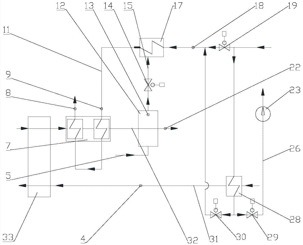
[0087] like figure 1 Partially shown, an air preheating system for comprehensive waste heat utilization with separate control phase change, including:
[0088] Air preheater 33, front air duct 31 of air preheater, rear flue 32 of air preheater, condensate main pipe 11, steam main pipe 15, air heater 28, flue gas phase change cooler 12, flue gas water Cooler 7, phase change water heater 17, condensate regulating valve 30, steam flow regulating valve 14, liquid flow pipe 5;
[0089] The main condensate pipe 11 is provided with an air heater 28, a condensate regulating valve 30, a phase change water heater 17, and a flue gas water cooler 7 in sequence along the condensate flow direction;
[0090] The air heater 28, the water side of the phase change water heater 17 and the flue gas water cooler 7 are all communicated with the condensate main pipe 11;
[0091] The incoming water end and the return water end of the condensate main pipe 11 are all connected to the condensate main pi...
Embodiment 2
[0103] like figure 1 As shown, an air preheating system for comprehensive waste heat utilization with separate control phase change, including:
[0104] Air preheater 33, front air duct 31 of air preheater, rear flue 32 of air preheater, condensate main pipe 11, steam main pipe 15, air heater 28, flue gas phase change cooler 12, flue gas water Cooler 7, phase change water heater 17, condensate regulating valve 30, steam flow regulating valve 14, liquid flow pipe 5;
[0105] The main condensate pipe 11 is provided with an air heater 28, a condensate regulating valve 30, a water temperature sensor 18 before the phase change water heater, a phase change water heater 17, and an inlet water temperature of the flue gas water cooler along the flow direction of the condensate water. Sensor 9, flue gas water cooler 7 and outlet water temperature sensor 8 of the flue gas water cooler;
[0106] The air heater 28, the water side of the phase change water heater 17 and the flue gas water...
Embodiment 3
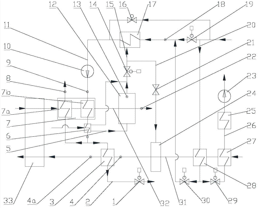
[0140] like figure 2 As shown, compared to embodiment 2, the system of this embodiment also includes:
[0141] The flue gas water cooler 7 is composed of a low-temperature flue gas water cooler 7b and a high-temperature flue gas water cooler 7a; the low-temperature flue gas water cooler 7b and the high-temperature flue gas water cooler 7a are sequentially arranged at Condensate main pipe 11;
[0142] A booster water pump 10 is arranged on the condensate main pipe 11 between the inlet water temperature sensor 9 of the flue gas water cooler and the phase change water heater 17;
[0143] The system also includes: hot water recirculation pipe 2;
[0144] One end of the hot water recirculation pipe 2 is connected to the condensate main pipe 11 between the low temperature flue gas water cooler 7b and the high temperature flue gas water cooler 7a; the other end of the hot water recirculation pipe 2 is connected to The main condensate pipe 11 between the phase change water heater ...
PUM
 Abstract
Description
Claims
Application Information
 - R&D
- Intellectual Property
- Life Sciences
- Materials
- Tech Scout
- Unparalleled Data Quality
- Higher Quality Content
- 60% Fewer Hallucinations
Browse by: Latest US Patents, China's latest patents, Technical Efficacy Thesaurus, Application Domain, Technology Topic, Popular Technical Reports.
© 2025 PatSnap. All rights reserved.Legal|Privacy policy|Modern Slavery Act Transparency Statement|Sitemap|About US| Contact US: help@patsnap.com


