Air preheating system and air preheating method for comprehensive waste heat utilization with separate control phase change

A technology of air preheating and air preheater, which is applied in the direction of combustion method, lighting and heating equipment, indirect carbon dioxide emission reduction, etc., and can solve the problem that the temperature of condensed water and incoming water should not be too high, increase the temperature difference of heat transfer, and difficult main heating steam saturation temperature etc.

Active Publication Date: 2019-06-18
SHANXI SANHESHENG IND TECH
View PDF8 Cites 0 Cited by
  • Summary
  • Abstract
  • Description
  • Claims
  • Application Information

AI Technical Summary

Problems solved by technology

[0004] However, the existing separate control phase change system is relatively insufficient, because it makes all the waste heat of the flue gas indirectly heat the condensed water, which increases the heat transfer temperature difference and increases the heat transfer process. loss; due to the influence of the poor heat transfer end of the condensate heater, the temperature of the condensate incoming water cannot be too high, so the bypass condensate discharges the low-temperature stage and the low-pressure extraction reduces the efficiency of waste heat utilization; in addition, the existing sub-control The phase change technology uses a vapor-liquid heat exchanger to reduce the supercooling degree of the inlet water of the flue phase change cooler. It needs external auxiliary steam to supplement the heating water. The system is relatively complicated, otherwise it will be affected by the heat transfer difference between the main heating steam and water. The water temperature is difficult to approach the saturation temperature of the main heating steam

Method used


Image

  • Air preheating system and air preheating method for comprehensive waste heat utilization with separate control phase change
  • Air preheating system and air preheating method for comprehensive waste heat utilization with separate control phase change

Examples


Embodiment 1

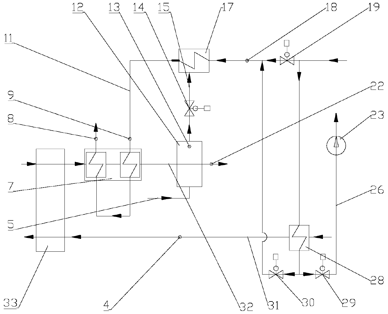
[0087] Such as figure 1 Partially shown, an air preheating system for comprehensive waste heat utilization with separate control phase change, including:

[0088] Air preheater 33, front air duct 31 of air preheater, rear flue 32 of air preheater, condensate main pipe 11, steam main pipe 15, air heater 28, flue gas phase change cooler 12, flue gas water Cooler 7, phase change water heater 17, condensate regulating valve 30, steam flow regulating valve 14, liquid flow pipe 5;

[0089] The main condensate pipe 11 is provided with an air heater 28, a condensate regulating valve 30, a phase change water heater 17, and a flue gas water cooler 7 in sequence along the condensate flow direction;

[0090] The air heater 28, the water side of the phase change water heater 17 and the flue gas water cooler 7 are all communicated with the condensate main pipe 11;

[0091] The incoming water end and the return water end of the condensate main pipe 11 are all connected to the condensate main...

Embodiment 2

[0103] Such as figure 1 As shown, an air preheating system for comprehensive waste heat utilization with separate control phase change, including:

[0104] Air preheater 33, front air duct 31 of air preheater, rear flue 32 of air preheater, condensate main pipe 11, steam main pipe 15, air heater 28, flue gas phase change cooler 12, flue gas water Cooler 7, phase change water heater 17, condensate regulating valve 30, steam flow regulating valve 14, liquid flow pipe 5;

[0105] The main condensate pipe 11 is provided with an air heater 28, a condensate regulating valve 30, a water temperature sensor 18 before the phase change water heater, a phase change water heater 17, and an inlet water temperature of the flue gas water cooler along the flow direction of the condensate water. Sensor 9, flue gas water cooler 7 and outlet water temperature sensor 8 of the flue gas water cooler;

[0106] The air heater 28, the water side of the phase change water heater 17 and the flue gas wa...

Embodiment 3

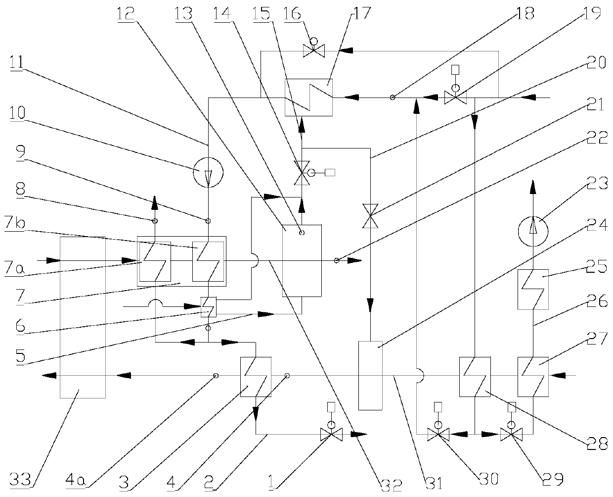
[0140] Such as figure 2 As shown, compared to embodiment 2, the system of this embodiment also includes:

[0141] The flue gas water cooler 7 is composed of a low-temperature flue gas water cooler 7b and a high-temperature flue gas water cooler 7a; the low-temperature flue gas water cooler 7b and the high-temperature flue gas water cooler 7a are sequentially arranged at Condensate main pipe 11;

[0142] A booster water pump 10 is arranged on the condensate main pipe 11 between the inlet water temperature sensor 9 of the flue gas water cooler and the phase change water heater 17;

[0143] The system also includes: hot water recirculation pipe 2;

[0144] One end of the hot water recirculation pipe 2 is connected to the condensate main pipe 11 between the low temperature flue gas water cooler 7b and the high temperature flue gas water cooler 7a; the other end of the hot water recirculation pipe 2 is connected to The main condensate pipe 11 between the phase change water heat...


PUM


Abstract

The invention discloses a respective-control phase change comprehensive waste heat utilization air preheating system and method. The system comprises an air preheater (33), an air preheater front air way (31), an air preheater rear flue (32), a condensate water main pipe (11), a steam main pipe (15), an air heater (28), a flue gas phase change cooler (12), a flue gas water cooler (7), a phase change water heater (17), a condensate water regulating valve (30), a steam flow regulating valve (14) and a liquid flow pipe (5). By means of the respective-control phase change comprehensive waste heat utilization air preheating system and method, a respective-control phase change heat exchange manner is adopted in a final-stage flue gas waste heat recovery heat exchanger, the final-stage flue gas waste heat recovery heat exchanger is combined with a condensate water air heater and a high-temperature flue gas cooler, and waste heat recovery benefits are improved.

Description

technical field [0001] The invention belongs to the technical field of safe and controllable heat transfer, and is particularly suitable for use in the fields of waste heat recovery and utilization of boiler flue gas, air preheating and the like. Background technique [0002] Phase change heat has the characteristics of high heat transfer coefficient, large latent heat carried by the medium, unique correspondence between phase change saturation temperature and saturation pressure, uniform temperature distribution of phase change fluid, and easy control of phase change parameters, so it is widely used in enhanced heat transfer and Waste heat recovery and utilization system. [0003] Separately controlled phase change technology independently controls the phase change parameters of the cold source and heat source, so that the phase change parameters of the heat source are not affected by the heat exchange phase change parameters of the cold source, and reliably guarantees the ...

Claims


Application Information

Patent Timeline
Patent Type & Authority Patents(China)
IPC IPC(8): F23L15/00
CPCF23L15/00Y02E20/34
Inventor 郝江平闫润生
Owner SHANXI SANHESHENG IND TECH
Why Eureka
Try Eureka