De-dusting cable tray

A cable tray and cable technology, applied in the direction of electrical components, chemical instruments and methods, cleaning methods and appliances, etc., can solve the problems of poor heat dissipation of cables and easy accumulation of dust, so as to improve cleanliness, ensure current carrying capacity, and reduce fire hazards hazard risk effect

Inactive Publication Date: 2017-07-21
成都协恒科技有限公司
View PDF12 Cites 6 Cited by
  • Summary
  • Abstract
  • Description
  • Claims
  • Application Information

AI Technical Summary

Problems solved by technology

[0004] In order to solve the problems that the existing cable bridges are easy to accumulate dust and the cable heat dissipation effect is poor, the purpose of the present invention is to provide a dust removal type cable bridge

Method used


Image

  • De-dusting cable tray
  • De-dusting cable tray
  • De-dusting cable tray

Examples


Embodiment 1

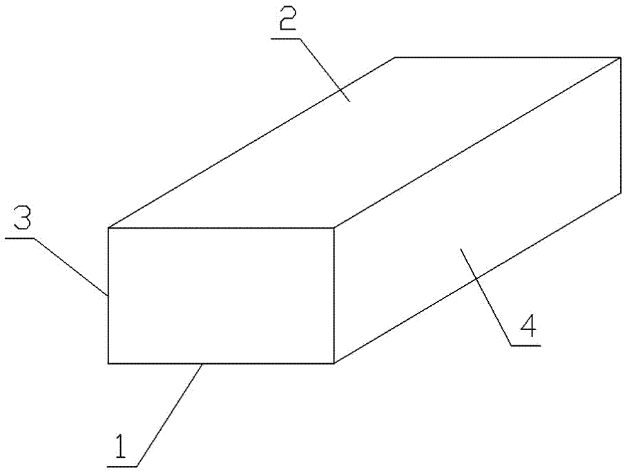
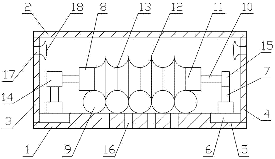
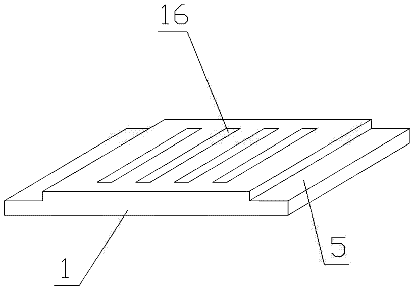
[0029] Such as Figure 1 to Figure 3 As shown, in the cable tray, slide rails 5 are provided on the left and right sides of the bottom plate 1, and a conveyor belt 6 is provided inside the slide rail 5. Vertical rods 7 are fixed on the conveyor belt 6, and the vertical rods 7 on the left and right sides are connected to each other. There is a cleaning brush 8 placed horizontally, and the bottom of the cleaning brush 8 is in close contact with the top of the cable 9; the conveyor belt 6 is connected with the central controller through an electric signal.

[0030] The cleaning brush 8 includes a brush handle 10 and a cylindrical brush head 11 wrapped on the outside of the brush handle 10; the surface of the brush head 11 is provided with protruding protruding portions 12, and recesses 13 are formed between adjacent protruding portions 12; The recessed part 13 is in close contact with the top surface of the cable 9 , and the pointed protrusion 12 is in close contact with the rece...

Embodiment 2

[0036] Such as Figure 1 to Figure 3 As shown, in the cable tray, slide rails 5 are provided on the left and right sides of the bottom plate 1, and a conveyor belt 6 is provided inside the slide rail 5. Vertical rods 7 are fixed on the conveyor belt 6, and the vertical rods 7 on the left and right sides are connected to each other. There is a cleaning brush 8 placed horizontally, and the bottom of the cleaning brush 8 is in close contact with the top of the cable 9; the conveyor belt 6 is connected with the central controller through an electric signal.

[0037] The cleaning brush 8 includes a brush handle 10 and a cylindrical brush head 11 wrapped on the outside of the brush handle 10; the surface of the brush head 11 is provided with protruding protruding portions 12, and recesses 13 are formed between adjacent protruding portions 12; The recessed part 13 is in close contact with the top surface of the cable 9 , and the pointed protrusion 12 is in close contact with the rece...

Embodiment 3

[0042] Such as Figure 1 to Figure 3 As shown, in the cable tray, slide rails 5 are provided on the left and right sides of the bottom plate 1, and a conveyor belt 6 is provided inside the slide rail 5, and vertical rods 7 are fixed on the conveyor belt 6, and the vertical rods 7 on the left and right sides are connected There is a cleaning brush 8 placed horizontally, and the bottom of the cleaning brush 8 is in close contact with the top of the cable 9; the conveyor belt 6 is connected with the central controller through an electric signal.

[0043] The cleaning brush 8 includes a brush handle 10 and a cylindrical brush head 11 wrapped outside the brush handle 10; the surface of the brush head 11 is provided with outwardly protruding pointed portions 12, and recessed portions 13 are formed between adjacent pointed portions 12; The recessed part 13 is in close contact with the top surface of the cable 9 , and the pointed protrusion 12 is in close contact with the recess forme...


PUM


Abstract

The invention discloses a de-dusting cable tray comprising a bottom plate, a top plate, a left plate and a right plate. The de-dusting cable tray is characterized in that in the cable tray, the left and right sides of the bottom plate are provided with slide rails; conveyor belts are arranged in the slide rails; vertical rods are fixed on the conveyor belts; a horizontal cleaning brush is connected between the left and right vertical rods; the bottom of the cleaning brush is in close contact with the top of a cable; and the conveyor belts are connected with a central controller through electrical signals. The beneficial effects are as follows: the cooling effect of cables is improved; the situation of poor cable cooling caused by dust accumulation is prevented; normal current-carrying capacity of cables is ensured; the risk of cable fire is reduced; the service life of cables is prolonged; and as the vertical position of the cleaning brush is adjustable, the cleaning brush can adapt to diameter change of cables, and cable installation and disassembly are facilitated.

Description

technical field [0001] The invention belongs to the technical field of cable equipment, and in particular relates to a dust removal type cable bridge. Background technique [0002] Cable tray is a device for fixing cables, widely used in petroleum, chemical industry, electric power, light industry, telecommunications and other industries, mainly used for the laying of overhead power cables, control cables, lighting lines, and telecommunication cables. Cables will generate heat when they are working. If the heat cannot be dissipated in time, the current carrying capacity of the cables will be greatly reduced, and fires will easily occur in hot environments. [0003] Most of the existing cable trays use heat dissipation holes for natural heat dissipation. In harsh working environments, or as the use time increases, dust can easily enter the interior of the bridge frame from the heat dissipation holes and accumulate and cover the cables, making it difficult to dissipate the hea...

Claims


Application Information

Patent Timeline
IPC IPC(8): H02G3/04B08B1/00
CPCH02G3/0406H02G3/0412B08B1/30B08B1/12
Inventor 刘承范
Owner 成都协恒科技有限公司
Why Eureka
Try Eureka