Cloth rolling frame and cloth rolling roller

A technology of cloth rolling roller and winding roller, which is applied in the directions of winding strips, thin material processing, transportation and packaging, etc. It can solve the problems of a large number of manpower operations and inaccurate adjustments, so as to improve the aesthetics and avoid inaccurate accuracy. High and low deformation effect

Active Publication Date: 2018-05-11
HAINING JBL TEXTILE
View PDF7 Cites 0 Cited by
  • Summary
  • Abstract
  • Description
  • Claims
  • Application Information

AI Technical Summary

Problems solved by technology

Although the adjustment in this way only needs to control the ratchet pawl mechanism and the cloth winding roller, it is necessary to determine the rotation angle of the cloth winding roller by observing the base cloth during tension adjustment, which makes the adjustment not only inaccurate, but also and require a lot of manpower

Method used


Image

  • Cloth rolling frame and cloth rolling roller
  • Cloth rolling frame and cloth rolling roller
  • Cloth rolling frame and cloth rolling roller

Examples


Embodiment 1

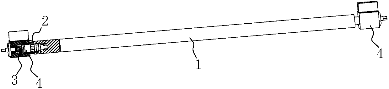
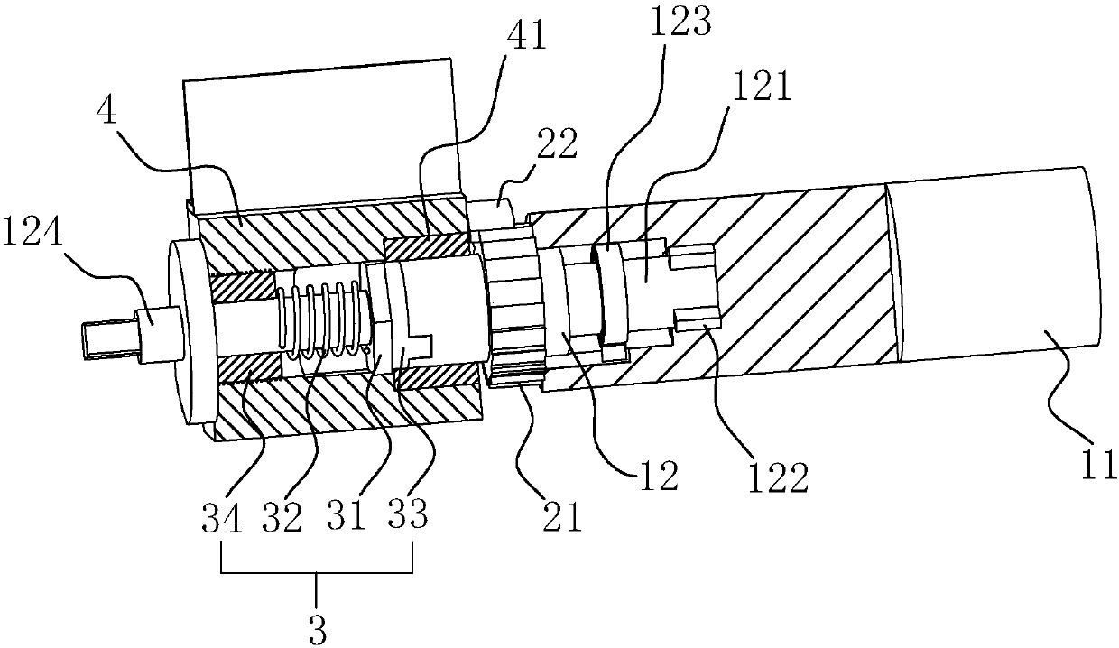
[0048] Embodiment 1: a kind of cloth roll, as figure 1 and figure 2 As shown, it includes a roller shaft 1, a claw mechanism 2 and a damping mechanism 3. The claw mechanism 2 is one in number and is arranged at one end of the roller shaft 1. The claw mechanism 2 includes a ratchet 21 and a pawl 22, and the ratchet 21 is fixed On the roller shaft 1; two damping mechanisms 3 are arranged on the two ends of the roller shaft 1 respectively.

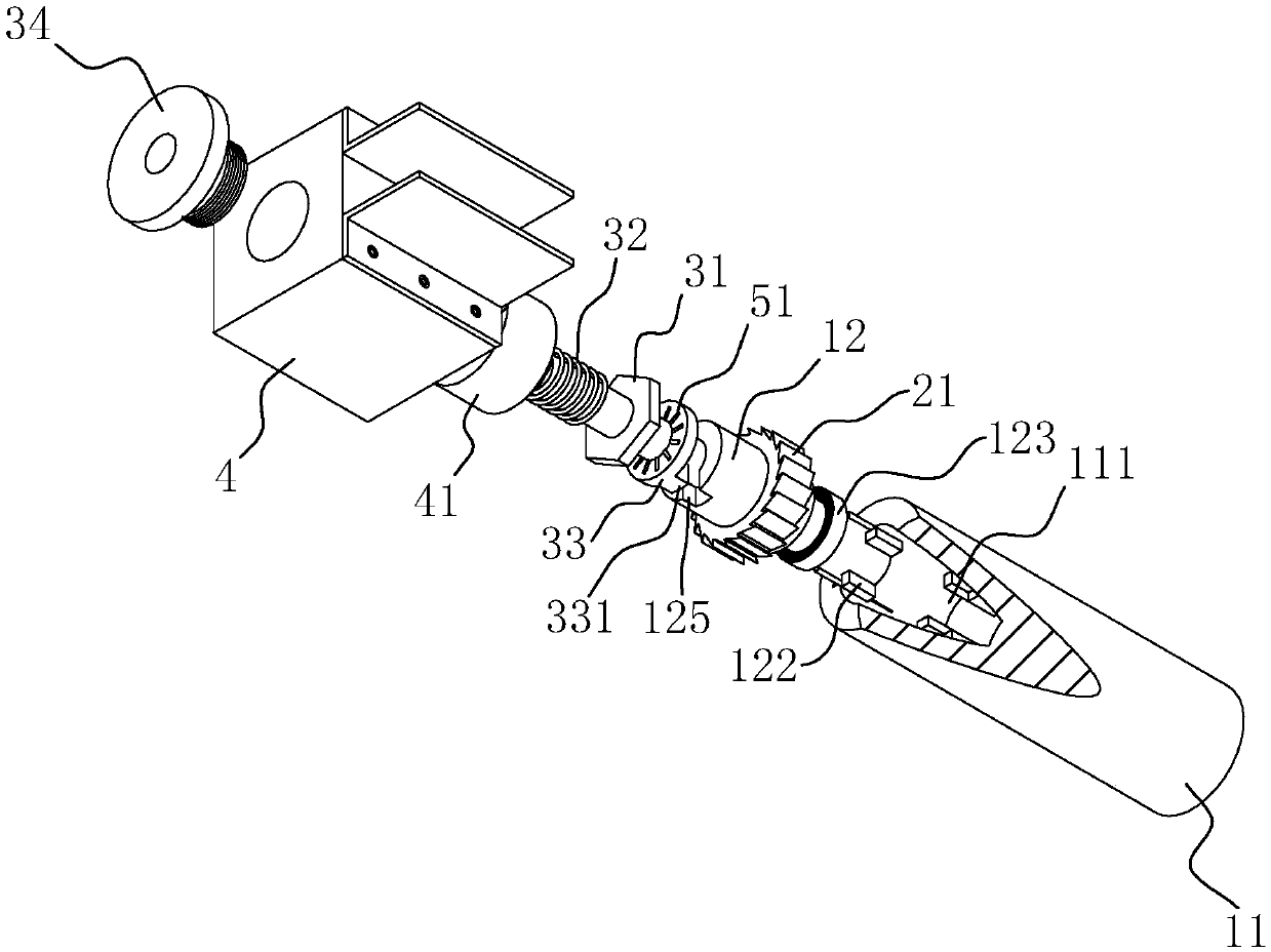
[0049] refer to figure 2 and image 3 The roller shaft 1 includes a roller body 11 and a connecting portion 12 arranged at both ends of the roller body 11, one end of the connecting portion 12 is inserted into the end of the roller body 11, and the other end is rotatably connected to a sliding block 4 through a bearing 41, The rotation of the roller shaft 1 is realized by two sliding blocks 4 . Wherein, one end of the connecting portion 12 is provided with an insertion portion 121, and a plurality of limit strips 122 are evenly distribu...

Embodiment 2

[0055] Embodiment 2: a kind of cloth rolling frame, such as Figure 5 and Figure 6 As shown, it includes: a winding roller 6, a cloth rolling roller of the first embodiment and two poles, one end of the winding roller 6 is provided with a claw device 8, and the claw device 8 and the claw mechanism 2 have the same structure , but the limited direction of the ratchet 22 on the pawl device 8 to the ratchet 21 is opposite to the limited direction of the ratchet 22 on the pawl mechanism 2 to the ratchet 21; The conveyance between the cloth roll and the winding roll 6; two poles connect the winding roll 6 and the cloth rolling roll to form a frame structure.

[0056] Wherein, two sliding blocks 4 are also arranged at both ends of the winding roller 6, and the struts are connected to the sliding blocks 4 on the winding roller 6 and the cloth rolling roller.

[0057] Working principle: first install the base cloth roll on the cloth roll, then pull the base fabric out from the roll ...

Embodiment 3

[0058] Embodiment 3: as Figure 7 As shown, the difference from Embodiment 2 is that two guide rollers 9 located on the same vertical surface are arranged on the pole, the guide rollers 9 are parallel to the cloth rolling roller, and the winding roller 6 and the cloth rolling roller are parallel and not Intersect at the plane where the guide roller 9 is located. The cloth for embroidery is kept on the same vertical plane by the setting of the two guide rollers 9, avoiding that the base cloth between the winding roller 6 and the cloth roll cannot be kept on the same plane because the diameter of the base cloth roll changes.


PUM


Abstract

The invention discloses a cloth winding frame and a cloth winding roller thereof. The cloth winding roller comprises a roller shaft and a ratchet-pawl mechanism, and the ratchet-pawl mechanism is arranged at one end of the roller shaft and comprises a ratchet and a pawl. A damping mechanism for increasing the rotation resistance of the roller shaft is arranged at least one end of the roller shaft. Each damping mechanism comprises an elastic pressing piece and a damping piece, wherein the damping piece is fixedly arranged at the end of the roller shaft; the elastic pressing piece is pressed on the end face of the damping piece in the axis direction of the roller shaft under the action of elastic force; and a resistance increasing mechanism is arranged on the abutting surface between the damping piece and the elastic pressing piece. According to the cloth winding frame and the cloth winding roller, the damping mechanism is arranged based on the ratchet-pawl mechanism, thus, rotation of the roller shaft can overcome resistance generated by the resistance increasing mechanism by applying certain force, accordingly, the roller shaft is driven to rotate, that is, when base cloth is pulled out from the cloth winding roller, the force for pulling the base cloth can overcome the resistance, the cloth winding roller is driven to rotate, the base cloth is in the tightened state all the time in the process, and tightening is achieved automatically after replacement is completed.

Description

technical field [0001] The invention relates to an embroidery machine, in particular to a cloth rolling frame and a cloth rolling roller. Background technique [0002] Embroidery machine, also known as computerized embroidery machine, is the most advanced embroidery machine in the contemporary era. It can achieve high-speed and high-efficiency traditional manual embroidery, and can also achieve "multi-level, multi-functional, unity and perfection". [0003] The authorized announcement number is CN101230525, and the Chinese patent with the application date on January 25, 2008 discloses a multi-head embroidery machine, which includes a frame, a cloth rolling frame installed on the frame and its driving device, machine head and rotary machine. The shuttle box, the cloth rolling frame is vertically installed on the frame, and the driving device is composed of the X-direction driving mechanism and the Y-direction driving mechanism. The Y-direction drive mechanism is linked and ...

Claims


Application Information

Patent Timeline
Patent Type & Authority Patents(China)
IPC IPC(8): B65H18/10B65H16/10B65H23/06
CPCB65H16/103B65H18/103B65H23/063
Inventor 戚兴华
Owner HAINING JBL TEXTILE
Why Eureka
Try Eureka