Direct-connected drive mechanism for vertical cycle garage and vertical cycle garage

A technology of vertical circulation and transmission mechanism, which is applied in the direction of buildings, building types, and buildings where cars are parked, and can solve problems such as low transmission efficiency, easy rusting of chains, and high failure rate

Inactive Publication Date: 2017-07-25
QINHUANGDAO XINGLONG YUAN METAL PROD
View PDF0 Cites 5 Cited by
  • Summary
  • Abstract
  • Description
  • Claims
  • Application Information

AI Technical Summary

Problems solved by technology

But at present, the transmission system of the vertical cycle three-dimensional garage in China is in the form of one-stage chain transmission or two-stage

Method used


Image

  • Direct-connected drive mechanism for vertical cycle garage and vertical cycle garage
  • Direct-connected drive mechanism for vertical cycle garage and vertical cycle garage
  • Direct-connected drive mechanism for vertical cycle garage and vertical cycle garage

Examples


Embodiment 1

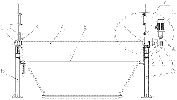
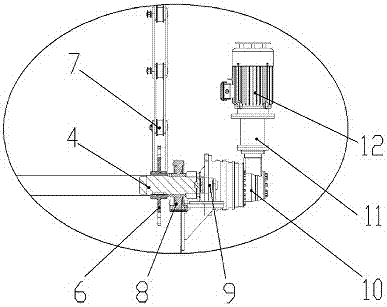
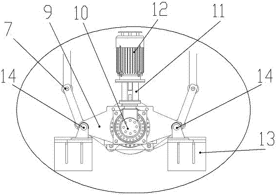
[0020] as attached figure 1 with Figure 4 As shown, the direct-coupled transmission mechanism for the vertical cycle garage of the present invention includes a rear bearing seat (1), a rear lifting chain (2), a rear sheave (3), a transmission shaft (4), and a vehicle-carrying plate device (5 ), front sheave (6), front lifting chain (7), front bearing seat (8), torque arm (9), reducer (10), coupling (11), drive motor (12), front frame (13), bearing pin (14) and rear frame (15).

[0021] The reducer (10) is fixed on the front frame (13) through the torque arm (9) and the pin shaft (14). The reducer (10) is a planetary gear reducer with a large transmission speed ratio and high transmission efficiency. Advantages, the output end is connected to the input end of the drive shaft (4) through a spline, the front sheave (6) and the rear sheave (3) rotate synchronously with the drive shaft (4) through a flat key, and the front sheave (6) and the drive shaft (4) rotate synchronously....

Embodiment 2

[0024] as attached figure 1 with Figure 4 As shown, the vertical cycle garage of the present invention includes a front frame (13) and a rear frame (15) of the garage, a direct-coupled transmission mechanism for the vertical cycle garage, and several car-loading plate devices (5) for carrying cars. , characterized in that: the transmission shaft (4) in the direct-coupled transmission mechanism for the vertical cycle garage is set in the middle of the front frame (13) and the rear frame (15) of the garage, and the drive motor (12), coupling (11) . The speed reducer (10) is arranged outside the front frame (13) of the garage, and the vehicle-carrying plate devices (5) are respectively arranged on both sides of the middle part of the front frame (13) and the rear frame (15) of the garage. The front lifting chain ( 7) Installed in the chain guide of the front frame (13), and the rear lifting chain (2) is installed in the chain guide of the rear frame (15). The chain guide rail ...


PUM


Abstract

The invention relates to the technical field of three-dimensional garages, in particular to a transmission mechanism of a vertical circulation three-dimensional garage and a vertical circulation garage. A direct-coupled transmission mechanism for a vertical circulation garage, which includes a drive motor, a coupling, a reducer, a transmission shaft and a shift fork, and a front lifting chain and a rear lifting chain for connecting a vehicle-carrying plate device, the drive motor and the reducer The motor is fixed together by a coupling, and the output end of the reducer is connected with the input end of the transmission shaft through a spline. The two ends of the drive shaft are supported by bearing seats, and the sheave is fixed with the drive shaft through flat keys. The sheave engages the hoist chain and is in place below the vertical endless chain guide. When the drive motor drives the reducer to rotate, the reducer drives the sheave on the transmission shaft to rotate together, thereby driving the lifting chain to run in the track to realize the vehicle lifting function. The direct-connection transmission mechanism for the vertical circulation garage and the vertical circulation garage have a simple structure, high transmission efficiency, safety and reliability, and easy maintenance.

Description

technical field [0001] The invention relates to the technical field of three-dimensional garages, in particular to a direct-connection transmission mechanism for a vertical circulation garage and a vertical circulation garage. Background technique [0002] At present, the number of cars in my country has exceeded 160 million, but the difficulty of parking in cities has become a common phenomenon, mainly reflected in the contradiction between the expansion of parking space and the shortage of urban land. For this reason, mechanical three-dimensional garages have emerged as the times require. [0003] The mechanical three-dimensional garage is an effective means to solve the existing problems, especially the vertical circulation three-dimensional garage, which has the characteristics of small footprint and flexible setting. But at present, the transmission system of the vertical cycle three-dimensional garage in China is in the form of one-stage chain transmission or two-stage...

Claims


Application Information

Patent Timeline
IPC IPC(8): E04H6/14E04H6/42
CPCE04H6/14E04H6/42
Inventor 常亚军陈双刘国栋
Owner QINHUANGDAO XINGLONG YUAN METAL PROD
Why Eureka
Try Eureka