SOH (State of Health) estimation method of power cell system based on fractional order model
A power battery, state of health technology, applied in the direction of measuring electricity, measuring electrical variables, measuring devices, etc.
- Summary
- Abstract
- Description
- Claims
- Application Information
AI Technical Summary
Problems solved by technology
Method used
Image

Examples
Embodiment Construction
[0053] The above is only an overview of the technical solution of the present invention. In order to better understand the technical means of the present invention, the present invention will be further described in detail below in conjunction with the accompanying drawings and specific embodiments.
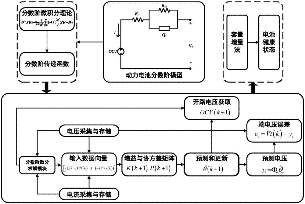
[0054] The method for estimating the state of health of the power battery system provided by the present invention is as follows: figure 1 As shown, it specifically includes the following steps:
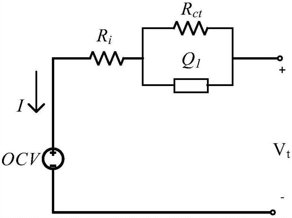
[0055] 1). Establishing a fractional order model of the power battery system, and discretizing the model;
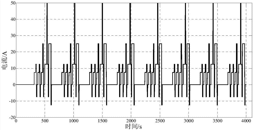
[0056] 2). Carry out real vehicle data collection, and use the least squares method based on the forgetting factor to carry out online identification of the parameter matrix;
[0057] 3). Extracting the open circuit voltage and other impedance parameters in real time from the parameter matrix obtained from the identification.
[0058] 4). Estimate the state of health (SOH) of the ...
PUM
 Abstract
Description
Claims
Application Information
 - Generate Ideas
- Intellectual Property
- Life Sciences
- Materials
- Tech Scout
- Unparalleled Data Quality
- Higher Quality Content
- 60% Fewer Hallucinations
Browse by: Latest US Patents, China's latest patents, Technical Efficacy Thesaurus, Application Domain, Technology Topic, Popular Technical Reports.
© 2025 PatSnap. All rights reserved.Legal|Privacy policy|Modern Slavery Act Transparency Statement|Sitemap|About US| Contact US: help@patsnap.com