Electric appliance button

A technology of buttons and electrical appliances, which is applied in the direction of circuits, electric switches, electrical components, etc., can solve the problems of being easily affected by dust and water, and buttons being stuck, and achieves the effect of simple structure, avoiding blowing, and ensuring normal operation

Inactive Publication Date: 2017-07-25
合肥梦飞电器有限公司
6 Cites 2 Cited by

AI-Extracted Technical Summary

Problems solved by technology

[0005] The present invention proposes an electrical button, which solves the problems that ...

Method used

When the present embodiment uses, the first lead wire 16 and the second lead wire 17 are connected with the circuit board of the electric appliance, and the receiving groove 1 is fixed on the circuit board; The panel is clamped to realize the installation. When the user presses the pressing plate 11, the cap wall 6 and the elastic member 19 are deformed under the force, protruding and bending outward, and the pressing plate 11 drives the first clamping plate 10 and the guide post 12 to move down. When the moving contact 13 and the first When the static contact 14 and the second static contact 15 are in contact with each other, they can no longer be pressed. At this time, the circuit connection between the first static contact 14 and the second static contact 15 is realized, and an electrical signal is sent to the circuit board; Then after releasing the pressing, the cap wall 6 and the elastic member 19 all return to their original positions, and the pressing plate 11, the first clamping plate 10 and the guide post 12 are reset, and the first static contact 14 and the second static contact 15 are disconnected. electrical connection. In this embodiment, the double reset is realized by the cap wall 6 and the elastic member 19 to ensure that the button can still realize the reset function in the case of any failure, so as to avoid the button from being pushed up and ensure normal operation; the upper and lower ends of the elastic fixing member are respectively provided with The first clamping groove 5 and the second clamping groove 9, the first clamping groove 5 at the upper end is clamped with the first clamping plate 10, the second clamping groove 9 is clamped with the panel of the electrical appliance on which the button is installed, and the cap The lower end of the wall is engaged with the side wall of the receiving tank 1 to separate the inside of the button from the outside world, preventing dust and water from ent...

Abstract

The invention provides an electrical button, which has a accommodating groove with a accommodating cavity, an elastic fixing member and a rigid pressing member are arranged on the accommodating groove; the elastic fixing member has an upper ring cover and a lower ring cover, forming a first clamping groove; the upper ring cover and the lower ring cover The outer periphery of the ring cover is connected by the cap wall, and the lower end of the cap wall is clamped in the connecting groove of the side wall of the receiving groove; the outer periphery of the lower end of the cap wall is provided with an upper fixing edge and a lower fixing edge to form a second clamping groove; The first clamping plate in the first clamping groove, the first clamping plate is provided with a pressing plate; the first clamping plate is provided with a guide post, and the lower end of the guide post is provided with a moving contact; the bottom surface of the receiving cavity is provided with a first static contact and the second static contact; the outer guide post is provided with an elastic piece, the upper end of the elastic piece is provided with an upper fixed end, and the lower end is set with a lower fixed end; the upper fixed end is clamped in the upper fixing groove of the first clamping plate, and the lower fixed end is clamped Connected to the lower fixing groove in the receiving cavity. The invention realizes double reset through the cap wall and the elastic member, so as to avoid the push button from being dead; the sealing performance is good, and dust and water are prevented from entering.

Application Domain

Electric switches

Technology Topic

Locking plateReset button +1

Image

  • Electric appliance button

Examples

  • Experimental program(1)

Example Embodiment

[0026] The technical solutions in the embodiments of the present invention will be clearly and completely described below in conjunction with the accompanying drawings in the embodiments of the present invention. Obviously, the described embodiments are only a part of the embodiments of the present invention, rather than all the embodiments. Based on the embodiments of the present invention, all other embodiments obtained by those of ordinary skill in the art without creative work shall fall within the protection scope of the present invention.
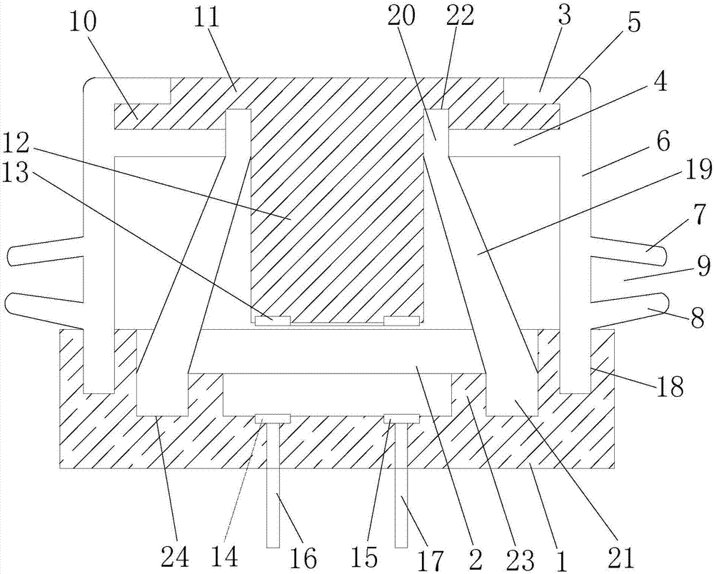
[0027] Such as figure 1 As shown, the electrical button in this embodiment includes a receiving slot 1 with a receiving cavity 2 in the receiving slot 1 and an upper end of the receiving slot 1 opening; the upper end of the receiving slot 1 is provided with a bypass The connecting groove 18 surrounding the receiving cavity 2; in this embodiment, both the receiving groove 1 and the receiving cavity 2 are cylindrical.
[0028] A cap is provided on the upper cover of the receiving slot 1, and the cap includes an elastic fixing part and a rigid pressing part.
[0029] The elastic fixing member has an annular upper ring cover 3 and an annular lower ring cover 4 located below the upper ring cover 3, and a first clamping groove 5 is formed between the upper ring cover 3 and the lower ring cover 4; The outer peripheries of the upper ring cover 3 and the lower ring cover 4 are connected by a cap wall 6, and the cap wall 6 extends downward from the outer circumference of the lower ring cover 4 and is engaged in the connecting groove 18; The outer periphery of the lower end of the wall 6 is provided with an annular upper fixing edge 7 and a lower fixing edge 8 located below the upper fixing edge 7. The upper fixing edge 7 and the lower fixing edge 8 are located above the connecting groove 18. A second clamping groove 9 is formed between the upper fixing edge 7 and the lower fixing edge 8; the second clamping groove 9 is clamped to the panel of the electrical appliance where the button is installed. In this embodiment, the outer end of the upper fixing edge 7 Inclined downwards, the outer end of the lower fixing edge 8 is inclined upwards, which can improve the tightness between the second clamping groove 9 and the panel of the electrical appliance, improve the degree of fixing and sealing, and avoid the entry of dust and water.
[0030] The rigid pressing member has a circular first clamping plate 10, the first clamping plate 10 is clamped in the first clamping groove 5; the first clamping plate 10 is provided with a A circular pressing plate 11 is accommodated in the upper ring cover 3. In this embodiment, the inner diameter of the upper ring cover 3 is larger than the inner diameter of the lower ring cover 4, which facilitates the first clamping plate 10 to be clamped into the first clamping groove 5 and facilitates processing and assembly.
[0031] A guide post 12 is provided under the first clamping plate 10, and a ring of movable contacts 13 is provided at the lower end of the guide post 12; the bottom surface of the receiving cavity 2 under the movable contact 13 is provided with A first static contact 14 and a second static contact 15, the first static contact 14 is connected with a first lead 16, the second static contact 15 is connected with a second lead 17, the first lead 16 And the second lead 17 lead out of the receiving slot 1. Then when the guide post 12 moves down so that the movable contact 13 is in contact with the first static contact 14 and the second static contact 15, the first static contact 14 and the second static contact 15 are connected. Electrical connection; because the movable contact 13 is ring-shaped, there is no need to limit the precise position of the guide post 12, even if the guide post 12 rotates at a certain angle, the movable contact 13 and the first static contact 14 and the second static contact 15 can be realized Electrical connection.
[0032] An elastic member 19 is sleeved on the outer side of the guide post 12, the outer surface and the inner surface of the elastic member 19 are both truncated cone-shaped; the upper end of the elastic member 19 is provided with a ring-shaped upper fixed end 20, the elastic member The lower end of 19 is provided with an annular lower fixing end 21; the first clamping plate 10 is provided with an annular upper fixing groove 22, and the bottom surface of the receiving cavity 2 is provided with an annular baffle 23. A lower fixing groove 24 is formed between 23 and the side wall of the receiving groove 1; the upper fixing end 20 is received in the upper fixing groove 22, and the lower fixing end 21 is received in the lower fixing groove 24 Inside. In this embodiment, the inner side of the upper fixed end 20 abuts against the outer side of the guide post 12.
[0033] When this embodiment is used, the first lead 16 and the second lead 17 are connected to the circuit board of the electrical appliance, and the receiving slot 1 is fixed on the circuit board; the second clamping slot 9 is clamped to the panel of the electrical appliance where the button is installed. , Realize the installation. When the user presses the pressing plate 11, the cap wall 6 and the elastic member 19 are deformed by force, and bulge outward. The pressing plate 11 drives the first clamping plate 10 and the guide post 12 to move down, when the moving contact 13 and the first When the static contact 14 and the second static contact 15 are in close contact, they can no longer be pressed. At this time, the circuit connection between the first static contact 14 and the second static contact 15 is realized, and an electrical signal is sent to the circuit board; Then after releasing the pressing, the cap wall 6 and the elastic member 19 all return to their original positions, the pressing plate 11, the first clamping plate 10 and the guide post 12 are reset, and the first static contact 14 and the second static contact 15 are disconnected. Electrical connection. In this embodiment, double reset is realized by the cap wall 6 and the elastic member 19 to ensure that the button can still realize the reset function in the case of any failure, avoiding the button from topping and ensuring normal operation; the upper and lower ends of the elastic fixing member are respectively provided with The first clamping groove 5 and the second clamping groove 9, the first clamping groove 5 at the upper end is clamped with the first clamping plate 10, and the second clamping groove 9 is clamped with the panel of the electrical appliance where the button is installed. The lower end of the wall is clamped on the side wall of the receiving slot 1 to separate the inside of the button from the outside, so as to prevent dust and water from entering the inside of the button and affecting the normal operation of the button.
[0034] The above descriptions are only preferred embodiments of the present invention and are not intended to limit the present invention. Any modification, equivalent replacement, improvement, etc. made within the spirit and principle of the present invention shall be included in the present invention. Within the scope of protection.

PUM

no PUM

Description & Claims & Application Information

We can also present the details of the Description, Claims and Application information to help users get a comprehensive understanding of the technical details of the patent, such as background art, summary of invention, brief description of drawings, description of embodiments, and other original content. On the other hand, users can also determine the specific scope of protection of the technology through the list of claims; as well as understand the changes in the life cycle of the technology with the presentation of the patent timeline. Login to view more.

Similar technology patents

Body condition measuring device

InactiveUS20050234351A1simple structure
Owner:DENSO CORP

Magnetic cooling apparatus and control method thereof

ActiveUS20130180263A1simple structure
Owner:SAMSUNG ELECTRONICS CO LTD

Dual-Drivetrain of Power-Assist Vehicle

InactiveUS20100181130A1enhance uphill momentumsimple structure
Owner:CHOU WEN CHENG

Classification and recommendation of technical efficacy words

  • Simple structure
  • reasonable design

Sharing system for air-conditioning coat

InactiveCN107440179ASimple structureeasy to wear
Owner:QINGDAO HAIER AIR CONDITIONER GENERAL CORP LTD

Feeding device of sorter of batteries plate

InactiveCN101357717ASimple structurecooperate well
Owner:NANJING NORMAL UNIVERSITY

Emergency parachuting device and method for multiple-rotor unmanned aerial vehicle

InactiveCN103895870Aavoid aircraft crashSimple structure
Owner:SOUTH CHINA AGRI UNIV +1

Method for coal and gas outburst simulation experiment

Owner:CHINA COAL TECH ENG GRP CHONGQING RES INST

Embedding accuracy control construction method for embedded part of overlong equipment foundation platform

InactiveCN102134879Areasonable designSimple construction steps
Owner:SCEGC NO 6 CONSTR ENG GRP CO LTD

Frequency hopping communication anti-interference method based on cognitive radio

ActiveCN103441779AImprove anti-jamming communication abilityreasonable design
Owner:深圳市研谱科技有限公司
Why Eureka
Try Eureka