A guide plate stamping process

A guide plate and process technology, applied in the field of guide plate stamping technology, can solve problems such as manual feeding, increasing labor intensity of parts processing, and bonding between finished products and waste materials.

Active Publication Date: 2018-08-31
ZHEJIANG SEOKHO ROBOT TECH CO LTD
View PDF6 Cites 0 Cited by
  • Summary
  • Abstract
  • Description
  • Claims
  • Application Information

AI Technical Summary

Problems solved by technology

[0003] The existing guide plate stamping process realized by a punching machine includes the following problems: 1. Most of the feeding of the punching machine adopts manual feeding, which has low work efficiency and is very unsafe
[0004] 2. Due to the phenomenon that the finished product and the waste material will be bonded after the punch completes the stamping of the plate, when the process hole is punched out on the finished plate, the waste in the process hole will also be bonded to the finished plate. The blanking is sorted manually, which increases the labor intensity of parts processing
However, since the process holes on the plate cannot be processed in place when the plate is stamped, it is necessary to reposition the punching process hole on the blanked plate, and the plate produced in batches is prone to positioning deviation, which will lead to The entire board is scrapped; in addition, after the stamping of the board is completed, it needs to be carried out manually when it needs to be flattened, cleaned and other processes, which increases the labor intensity of parts processing

Method used


Image

  • A guide plate stamping process
  • A guide plate stamping process
  • A guide plate stamping process

Examples


Embodiment Construction

[0054] The present invention will be described in further detail below in conjunction with the accompanying drawings and embodiments. Wherein the same components are denoted by the same reference numerals. It should be noted that the words "front", "rear", "left", "right", "upper" and "lower" used in the following description refer to the directions in the drawings, and the words "bottom" and "top "Face", "inner" and "outer" refer to directions toward or away from, respectively, the geometric center of a particular component.

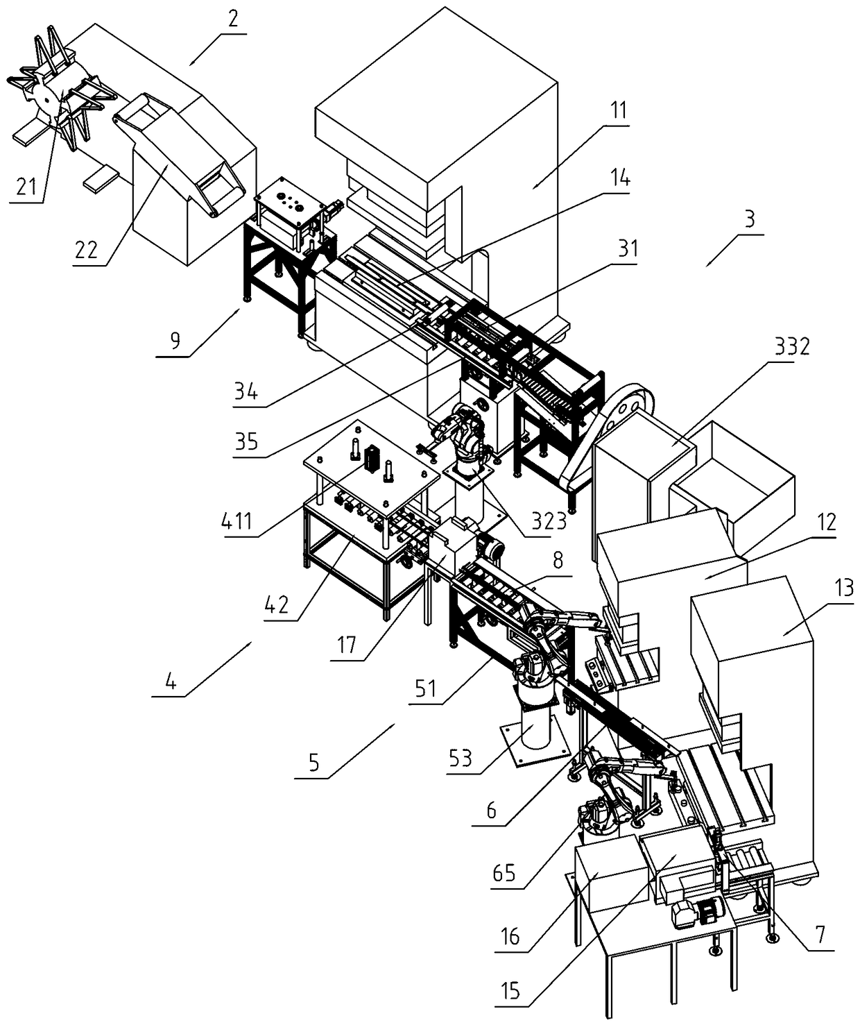
[0055] refer to Figure 1-10 Shown, a kind of guide plate stamping process, its steps are as follows:

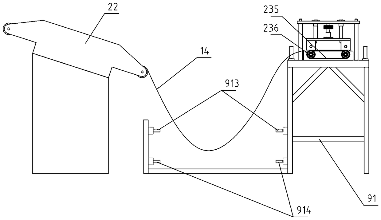
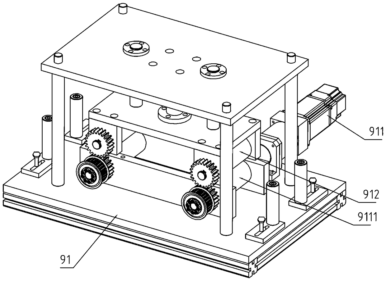
[0056] Step 1: Feeding, the feeding device 9 pulls out the strip-shaped coil material 14 on the discharge device 2, and the pulled strip-shaped coil material 14 forms a V-shaped structure between the feed device 9 and the discharge device 2, And its bottom is close to the ground, through the first group of photoelectric sensors 913 and the second g...


PUM


Abstract

The invention discloses a guide plate stamping process. According to the technical scheme, the guide plate stamping process is mainly characterized by comprising the steps of (1), feeding; (2), stamping; (3), blanking; (4), material cutting and collecting; (5), turning; (6), jacking of waste materials; (7), deburring; (8), positioning hole stamping; (9), process hole stamping; (10), flattening and cleaning. By means of the process, synchronous feeding can be performed on a stamping machine, the machining efficiency of the stamping machine is improved, labor intensity of part machining is lowered, and the automated degree of stamping machine machining is increased.

Description

technical field [0001] The invention relates to the technical field of mechanical equipment, more specifically, it relates to a stamping process of a guide plate. Background technique [0002] A punching machine is a stamping press. Stamping production is mainly for plates. Blanking, punching, forming, deep drawing, trimming, fine blanking, shaping, riveting and other operations can be performed through the mold. It is widely used in the machining industry. . When working, the punching machine exerts pressure on the plate, and completes the blanking of the finished product on the plate or completes the punching on the finished product. It needs to cooperate with a set of upper and lower dies, place the plate between them, and apply pressure from the punch to make it deform or Blanking. [0003] The existing guide plate stamping process realized by a punching machine includes the following problems: 1. Most of the feeding of the punching machine is manual feeding, which has...

Claims


Application Information

Patent Timeline
Patent Type & Authority Patents(China)
IPC IPC(8): B21D43/10B21D43/08B21D43/00B21D45/00B21D43/02
CPCB21D43/003B21D43/021B21D43/026B21D43/09B21D43/105B21D43/11B21D45/00B21D45/006
Inventor 朱振俞兴洪灵程旗凯陈源通陈卸件王京余晓春潘浩雷张庆权黄小健陈艳丽金璐洪丰
Owner ZHEJIANG SEOKHO ROBOT TECH CO LTD
Why Eureka
Try Eureka