Conveying device
A technology of conveying equipment and conveying mechanism, applied in the fields of optics, electronics and machinery, can solve the problems of guide wheel collision, fragmentation, weakening of guiding and stabilizing effects, etc., and achieve the effect of preventing collision, reducing fragmentation and not easy to diverge.
- Summary
- Abstract
- Description
- Claims
- Application Information
AI Technical Summary
Problems solved by technology
Method used
Image

Examples
Example Embodiment
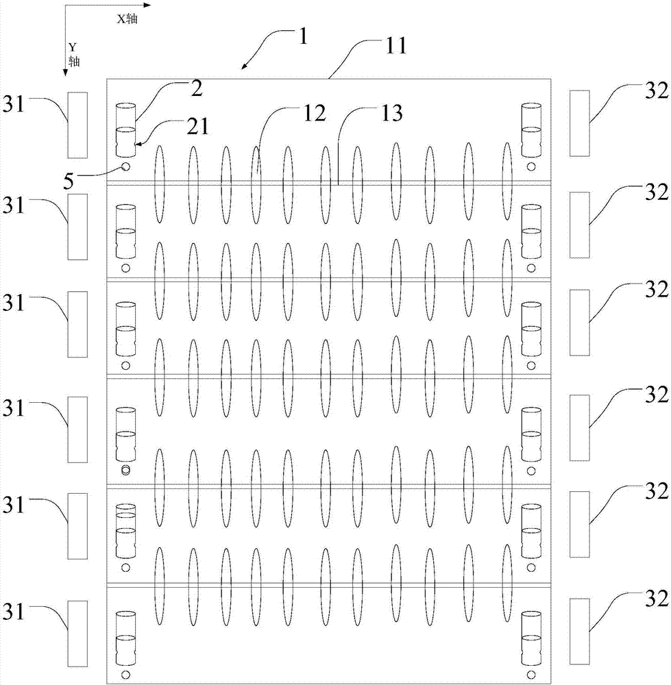
[0029] Example 1, as figure 1 As shown, a conveying device includes a conveying mechanism 1, a guide wheel 2, a laser detection group, an alarm, an indicator light 5 and a control system (not shown). Among them, the laser detection group, the alarm, and the transmission mechanism 1 are all connected to the control system.
[0030] Specifically, the transmission mechanism 1 includes a bottom plate 11, multiple groups of transmission rollers 12 and a power assembly (not shown), wherein, a circular hole is provided in the center of each transmission roller 12, and each group of transmission rollers 12 is assembled into a transmission through the circular hole. On the shaft, the direction of the transmission shaft is perpendicular to the transmission direction, the transmission shafts are arranged in parallel and equidistant to each other, and at least one end of the transmission shaft is assembled on the power assembly. In this embodiment, the axial direction of the transmission...
Example Embodiment
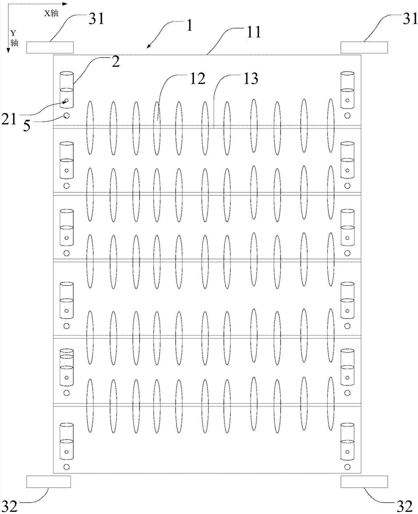
[0038] Example 2, as figure 2 As shown, in this embodiment, the difference from Embodiment 1 is that the deflection direction of the guide wheel 2 detected in this embodiment is the lateral deflection of the guide wheel 2, and the lateral direction in this embodiment is the X-axis direction, or The main structure of the guide wheel 2 rotates, causing the direction of the through hole 21 to be offset.
[0039] Specifically, in this embodiment, in the Y-axis direction, one of the laser detection groups is configured on each guide wheel 2 on the same side of the conveying mechanism 1 . The laser detection group is used to generate a laser beam. A through hole 21 is provided on the lower mounting seat of the guide wheel 2, and the through hole 21 is used for allowing the laser beam to pass through. In the Y-axis direction, the centers of the through holes 21 on each of the plurality of guide wheels 2 on the same side are on a straight line. In this way, the laser beam can pass...
Example Embodiment
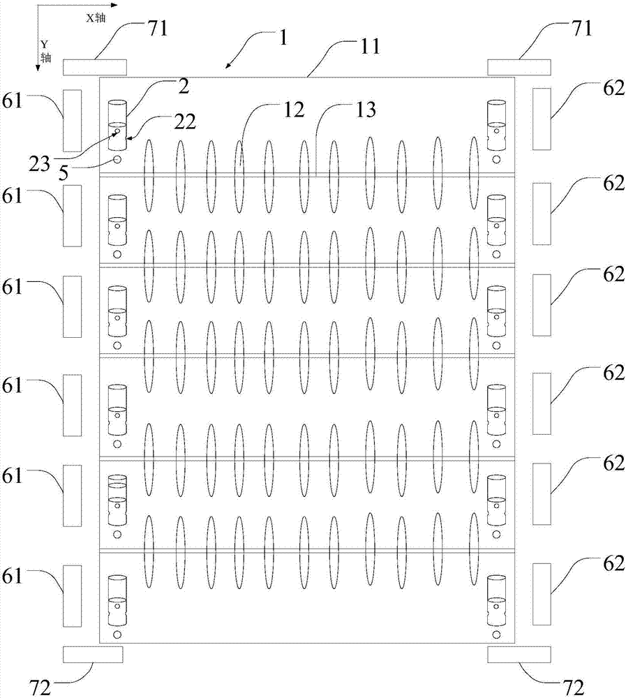
[0041] Example 3, as image 3 As shown, the difference between this embodiment and Embodiment 1 and Embodiment 2 is that the solution of this embodiment is a combination of Embodiment 1 and Embodiment 2, that is, in this embodiment, on the conveying mechanism 1, along the X-axis direction , every two corresponding guide wheels 2 are configured with a first laser detection group; along the Y-axis direction, each guide wheel 2 on the same side is configured with a second laser detection group. Therefore, in this embodiment, each guide wheel 2 is provided with a first through hole 22 and a second through hole 23 , and the first through hole 22 and the second through hole 23 are arranged in a crisscross pattern up and down. The upper and lower cross settings prevent mutual interference due to the intersection of beams and cause abnormal alarms.
[0042] In the X-axis direction, every two corresponding guide wheels 2 are equipped with a first laser detection group, so the hole cen...
PUM
 Abstract
Description
Claims
Application Information
 - R&D Engineer
- R&D Manager
- IP Professional
- Industry Leading Data Capabilities
- Powerful AI technology
- Patent DNA Extraction
Browse by: Latest US Patents, China's latest patents, Technical Efficacy Thesaurus, Application Domain, Technology Topic.
© 2024 PatSnap. All rights reserved.Legal|Privacy policy|Modern Slavery Act Transparency Statement|Sitemap